background image

ISSUED: 12-22-14   SHEET #: 180-9064-4   01-20-16

6

4

5

6

7

8

Transmitter 

Front 


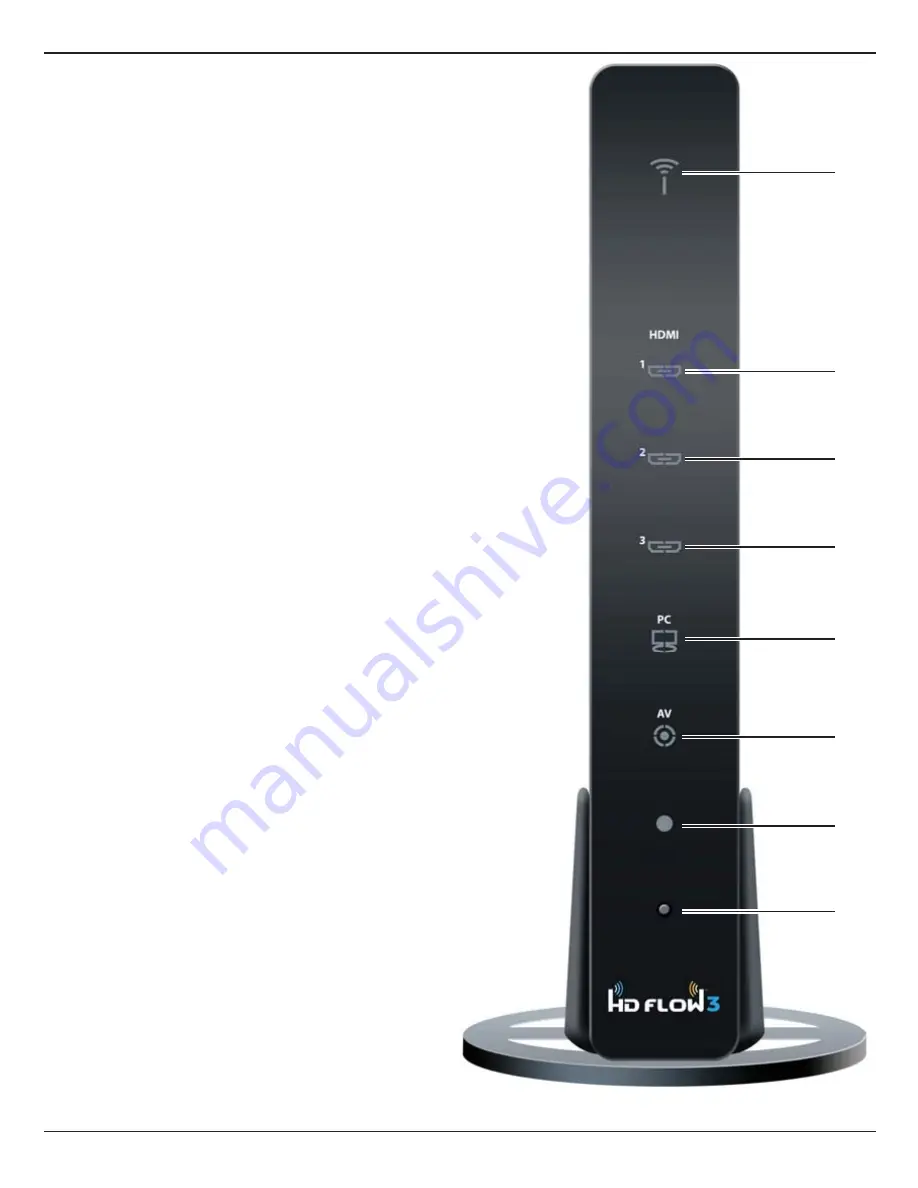
1.  Power/Link Indicator Light


•  Blinking indicator light - Establishing link between the  

    Transmitter and the Receiver.


•  Solid indicator light - Link between the Transmitter  

    and Receiver has been established and is ready for  
   signal transmission. 

2. HDMI 

1


•  The HDMI 1 indicator light will be illuminated when  

    the HDMI 1 port is selected for video input. 


•  If there is no signal, and/or the cable is not  


    connected, the indicator light will blink.

3. HDMI 

2


•  The HDMI 2 indicator light will be illuminated when  

    the HDMI 2 port is selected for video input. 


•  If there is no signal, and/or the cable is not  


    connected, the indicator light will blink.

4. HDMI 

3


•  The HDMI 3 indicator light will be illuminated when  

    the HDMI 3 port is selected for video input. 


•  If there is no signal, and/or the cable is not  


    connected, the indicator light will blink.

5. PC 


•  The PC indicator light will be illuminated when the PC  

    In port is selected for video input. 


•  If there is no signal, and/or the cable is not  


    connected, the indicator light will blink.

6. AV


•  The AV indicator light will be illuminated when the AV  

    In port (Composite) is selected for the video input.


•  If there is no signal, and/or the cable is not  


    connected, the indicator light will blink.

7. IR 

Window


•  IR receiving window enables remote control of the  

    transmitter and the receivers.

8.  Link/Source Selection Button 


•  When powered on: Press for one second to select  

    the video input source. Each press of the button    
    will cycle through the available video input "HDMI1


   HDMI2

 HDMI3

 PC

 AV 

HDMI1" in sequence.


•  Press and hold for 8 seconds until all indicator lights  

    blink synchronously, you are now in Scan/Pairing  
   Mode.

3

2

1

Summary of Contents for PeerAir Pro HDS300

Page 1: ...ISSUED 12 22 14 SHEET 180 9064 4 01 20 16 User Manual and Installation Guide Models HDS300 HDS300 2 HDS300 3 HDS300 4 HDS300 5 HDS300 6 READY Powered by Powered by ...

Page 2: ...2 Connecting Source Components To The Transmitter 12 IR Flasher Installation Setting Up IR Remote Control Capabilities for Source Devices 13 IR Extender Installation 13 Connecting The Receiver To The Display Device 14 Powering Up The PeerAir Pro Wireless AV Multi Display System 14 Input And Output Selection 15 Multicast Mode Pairing Additional Receiver s With The Transmitter 16 Peer To Peer LAN Wi...

Page 3: ...ves Do not insert foreign objects into the unit Do not place the unit on an unstable surface or in a poorly ventilated area Make sure to plug the AC power adaptors firmly into wall outlets Do not use the unit near any flammable substances or combustible sprays If any part of the AC power adaptor looks damaged do not use the product and immediately call Peerless AV Customer Care at 1 800 865 2112 K...

Page 4: ...ed to the Transmitter Step 11 Play the source device content and enjoy up to Full HD 1080p wireless entertainment experience Check the media source resolution The display device must be able to support the resolution of the media source that is being streamed Utilizing the INFO button will allow you to see the resolution data that the display device supports If the display device supports the high...

Page 5: ...reo Mini Jack and RCA Stereo Jack Receiver Video Resolution 480i p 720p 1080i p 24 30 fps Video Latency 40ms Frequency 5 18 5 24 5 75 5 81GHz Range 210 ft 64M Multicast Up to 6 receivers Requires additional receiver units Security WPA2 Personal and AES HDCP Version 1 3 Antenna Type MIMO 2x Internal IR Emitter 3 IR Emitters on a single wire IR Extender 1 included Remote Control 17 button IR remote ...

Page 6: ...inated when the HDMI 3 port is selected for video input If there is no signal and or the cable is not connected the indicator light will blink 5 PC The PC indicator light will be illuminated when the PC In port is selected for video input If there is no signal and or the cable is not connected the indicator light will blink 6 AV The AV indicator light will be illuminated when the AV In port Compos...

Page 7: ...i e Blu Ray player DVD STB etc 7 PC AUDIO IN Stereo audio input port for PC component or composite source 8 PC IN VGA Supports component and composite input with included Component Composite Adaptor 9 LAN LAN port used for wired connection alternative 10 DC 12V DC power input For the audio part of a component media source use the PC Audio input port with a 3 5mm to RCA cable not included If using ...

Page 8: ... component output is selected for video output If there is no signal and or the cable is not connected the indicator light will blink 4 AV The AV indicator light will be illuminated when the AV port composite is selected for the video output If there is no signal and or the cable is not connected the indicator light will blink 5 IR Window IR receiving window enables remote control of the transmitt...

Page 9: ...in order to extend IR reception range 4 AUDIO OUT 3 5mm stereo audio output port for component output 5 COMPONENT OUT Component Video output port 6 USB USB port used for service 7 LAN LAN port used for wired connection alternative 8 DC 12V DC Power Input For the audio part of a component media source use the PC Audio Output port with a 3 5mm to RCA cable not included ...

Page 10: ...s output settings This may also be accomplished without the use of the remote control by toggling between outputs via the Link Output Selection Button on the Receiver 5 VIDEO IN Transmitter Selects the Video input port of the Transmitter HDMI1 Selects HDMI1 as the Audio Video input HDMI2 Selects HDMI2 as the Audio Video input HDMI3 Selects HDMI3 as the Audio Video input PC Selects VGA Component as...

Page 11: ...e battery clip is located on the bottom of the remote control 2 Place the battery into the clip positive end facing up as shown 3 Place the clip back into the remote to complete the installation 1 Push the tab located on the left of the battery clip to the right and pull out the clip Battery Clip Tab ...

Page 12: ...it audio when using this input Connect the 3 5mm stereo audio cable from the VGA source component s audio output to the Transmitter s PC AUDIO IN port Connect HDMI cable from the Transmitter s pass thru output port to the input of the display device to enjoy the video coming through HDMI1 only Before starting the installation please ensure that all source components Blu ray player cable box etc an...

Page 13: ...evice is easier to locate with direct light shining on sections of the front panel of the device a small flashlight or a camera phone flashlight works well IR OUT Port IR Flasher Eye 4 Composite Media Source Video Connect yellow composite video RCA to green port on Component Composite Adaptor Audio A 3 5mm stereo audio cable is required not included to transmit audio when using this input Connect ...

Page 14: ... in the other end of the power cables to the Transmitter and then to the Receiver The units will automatically turn on 3 Turn on your display device TV monitor projector etc 4 While turning on the display device the PeerAir Pro System will be going through the start up process The process takes approximately 45 seconds to complete The Power Link Indicator Light on the Transmitter and Receiver shou...

Page 15: ... Select the desired media source input on the Transmitter There are two ways to select the source input on the PeerAir Pro Transmitter a Using the provided remote Press the desired input while pointing the remote at the Transmitter b Using the Link Source Selection Button on the Transmitter To toggle between Inputs press the Link Source Selection Button for one second on the unit and release 4 Pla...

Page 16: ...the process is complete Video on the additional paired Receivers will be lost during this process 3 Repeat steps 1 and 2 for each additional Receiver if any Note For 3 or more Receivers the system will change its mode from single channel to bonded channel If Receivers are removed from the system making it 2 or fewer Receivers total the system should be factory reset to put it back into single chan...

Page 17: ... the Transmitter and Receiver s has been established and is ready for signal transmission All Indicator Lights Flashing Units are booting or resetting and establishing a secure connection for AV transfer Lights blinking sequentially from top to bottom Unit is in Scan Pairing Mode searching for other PeerAir Pro devices 2 Transmitter HDMI1 HDMI2 HDMI3 PC AV The indicator light will be lit to indica...

Page 18: ...601 O O X O X 1600 x 900p60 O X X O X X 1680 x 1050p60 O O X O X X DTV Format TV standard 720 x 480I60 NTSC O O O X O O 720 x 576I50 PAL O O O X O O 720 x 480p60 O O X O O X 720 x 576p50 O O X O O X 1280 x 720p50 O O X O O X 1280 x 720p60 O O X O O X 1920 x 1080i50 O O X O O X 1920 x 1080i60 O O X O O X 1920 x 1080p24 O O X O X X 1920 x 1080p25 O X X O X X 1920 x 1080p30 O X X O X X 1920 x 1080p50...

Page 19: ...r logos have been broken removed or tampered with defaced or altered in any manner Damage caused by abuse misuse accident water or theft Physical damage Loss of the Accessories Except as stated above Peerless Industries Inc makes no express or implied warranties as to any product in Particular makes no warranty of merchantability or fitness for any particular purpose Peerless Industries Inc shall ...

Page 20: ...te Oak Circle Aurora IL 60502 USA 1 800 865 2112 www peerless av com 2016 Peerless AV All rights reserved Peerless AV is a trademark of Peerless Industries Inc HD Flow is a trademark of I Do It LTD Other parties marks are the property of their respective owners ...

Reviews: