5
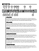
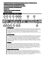
((11)) LLo
ow
w--ccu
utt ffiilltte
err
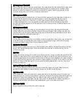
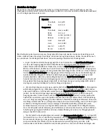
An 18 dB filter with a cut-off frequency of 200 Hz in the side chain (only)‚ does not filter the audio path. This
filter is used to prevent low frequency modulation (which often appears as pumping and breathing) by reducing
the affects of wind‚ stage and handling noise. If it is used with bass-only program material‚ it could prevent the
compressor from seeing the source. It does not require the external side-chain to be enabled.
((2
2)) D
De
e--e
esssse
err ffiilltte
err
This filter is named after its function—it helps remove the hissing in the “sss.” By increasing the
compressor’s sensitivity to high frequency components (as in the s‚ c and kconsonants) it acts more
aggressively on these sounds without lowering normal speech levels. For this circuit to function properly‚
the compressor’s attack and release controls must be set to respond very quickly (minimum settings) and
a mid- to high-compression ratio must be used. It does not require the external side-chain to be enabled.
((3
3)) B
By
yp
pa
assss
To disable signal processing each channel of the CEL2A can be bypassed. The internal circuitry maintains
input and output isolation even when bypassed‚ allowing the unit to function as an unbalanced to
balanced converter if needed. To provide this feature‚ power must be on even when the unit is bypassed. A
two-color status LED is provided to show the channel’s condition. When the unit is operating the LED is
green (processing happening)‚ when the LED is red‚ the unit is bypassed.
((4
4)) E
Exxtte
errn
na
all S
Siid
de
e--cch
ha
aiin
n E
En
na
ab
blle
e
The side-chain is an insert loop inserted into the detector path so that the signal sent to the detector can
be rerouted through an external device or replaced altogether. This switch enables the rear panel jack and
external processing. It has no affect on the side-chain low-cut or de-ess filters‚ which operate
independently‚ but any signal applied to the external jack will pass through them if they are enabled.
((5
5)) E
Exxp
pa
an
nd
de
err T
Th
hrre
essh
ho
olld
d
This sets the level at which the downward expander begins operation. If the input signal drops below
the thresholds set point‚ the expander fades it out according to the slope (ratio) set by the ratio control.
The soft-knee design smooths the transition from off to active by dynamically shifting the slope through
the transition point. The attack and release times are preset. An LED has been provided to show
expansion activity.
((6
6)) E
Exxp
pa
an
nd
de
err R
Ra
attiio
o ((G
Ga
atte
e))
The expander ratio is determined by dividing the input level by the output level. A ratio of 1:5 signifies
that the output level has dropped five times as fast as the input (downward expanded). Ratios of 1:1.2 to
1:2 are typically used to eliminate background noise and to dampen room reverberations. Higher ratios are
used when gating is required. Expansion is eliminated when the ratio is set to 1:1.
FF R
R O
O N
N T
T P
P A
A N
N E
E LL


