


8
Chapter 4. LCD, Front panel buttons and menus description
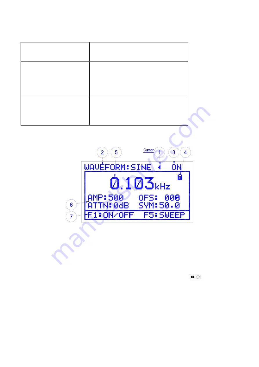
1. LCD display description
Section 1-TOP DISPLAY
Displays
The current waveform, the output status
(on/off) and the selection/edit cursor.
Section 2.MAIN-DISPLAY
Displays
•
The Frequency, Amplitude, attenuator,
offset and symmetry values.
•
The Sweep rate and width when the F5
button pressed.
Section 3-BOTTOM-DISPLAY
Displays
F
buttons for:
•
Turning the output ON/OFF F1
•
Setting the sweep values F5
•
Exit sweep settings F5.
[Table 1] LCD display areas
[Figure 5] LCD Display (AMP display mode)
1) Cursor
(1) The cursor is displayed in the upper part of the LCD when the unit is first turned on as shown in
Figure 5
. It is used to indicate and change Waveforms, amplitude, symmetry, offset, and
attenuator values. When the cursor is displayed as a (
<
or
>
) symbol it is the selection cursor
and can be moved to the desired menu item by turning the rotary dial or pressing the
appropriate front panel button (waveform, OFS, SYM). Pressing the
Button again the
cursor appears as a (
◄
or
►
), the edit cursor and is used to change waveform, Attenuator and
ON/OFF settings by turning the rotary dial.


