


MULTICHANNEL SIGNAL CONDITIONER MODEL 482C27 GENERAL OPERATION MANUAL
21
Gain =
1 Volt/
/
[Sensitivity (mV/unit) * Full Scale Input (units)]
Adding some simple error checking to insure the limits of the sensor and gain limits of the signal conditioner are not
exceeded completes the normalization process.
Gain
normalized
=
FSOT (V)
/
SENS * FSIN
Additional Considerations:
The storage of individual channel gains is stored in non-volatile memory locations. The new variables for each channel’s
sensitivity, full scale output level, and full scale input are stored in non-volatile memory locations when the unit is
powered down.
The error checking should provide a flag if the desired normalized output level is not feasible due to gain limitations.
The gain required may be too large given the sensor sensitivity defined, or too small which implies the sensor will not be
capable measure the expected value. The typical sensor will output a signal up to
5 Volts. The maximum swing may be
used in the error checking.
3.6 Auto Scaling and Overload Detection
3-6.1 Auto Scale
To avoid overload, model 482C27 features auto scaling for automatic gain adjustment (appears as ARNG on front panel
display). It first sets maximum gain on all channels, then decreases the gain setting of any channel on which an overload
has occurred. Auto scale continues until there is no overload with respect to the preset overload threshold level (standard
±10 volts) and sensed signal of the channel. Final gain and overload status interrogation is possible through the
command set. The correct procedure for using the auto scale feature is as follows:
1.
Excite the structure under test.
2.
Enable auto scale (Auto scale ON).
3.
Wait several seconds, until the unit is stabilized.
4.
Disable auto scale (Auto scale OFF).
5.
Read the gains of all channels.
6.
Begin test run.
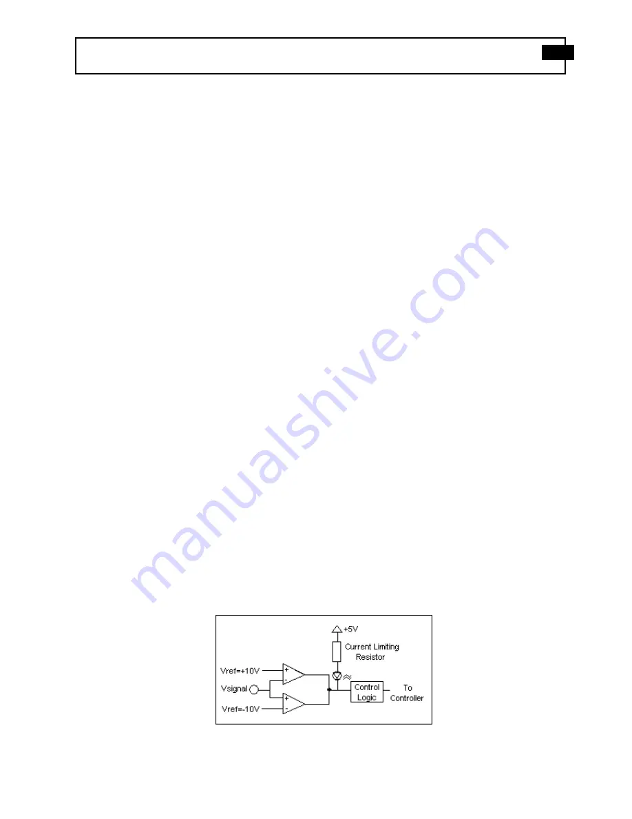
3-6.2 Overload
The overload feature uses the same window comparator principle previously discussed. The +V
ref
is equal to the default
overload value of ±10 volts. When the input voltage (Vsignal of Figure 3-7.1) to the window comparator exceeds the
reference voltage limits, overload has occurred, and the comparator’s output, which is normally “high,” becomes “low.”
This “low” state illuminates the overload LED and triggers the latch of overload detection circuitry. During regular
measuring time, the latch holds the occurrence of overloads until the user reads its status through the computer interface.
Figure 5 Auto scale/Overload Window Comparator


