PAVONE
SYSTEMS
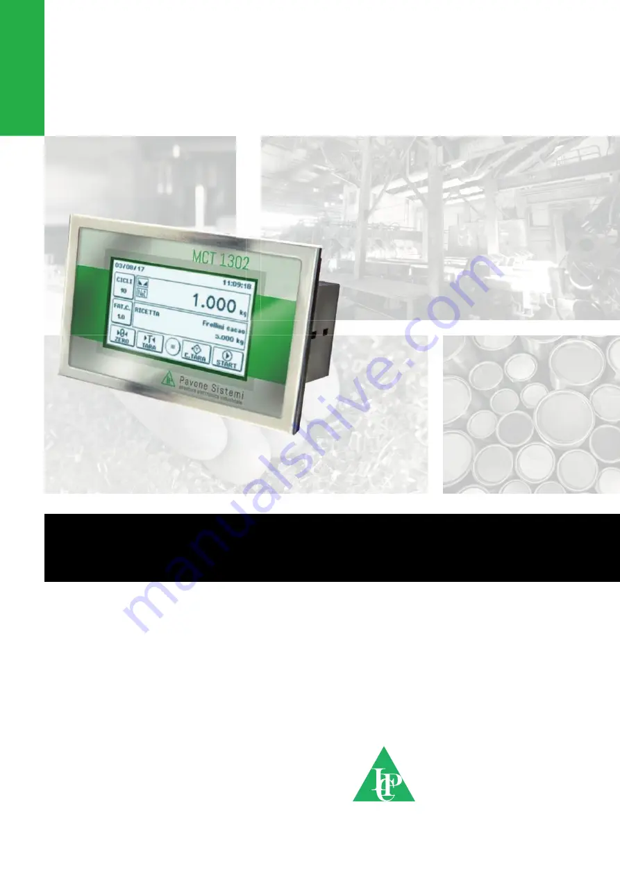
TECHNICAL MANUAL
MCT 1302
Touch screen batching version with RS232 serial, analog and Fieldbus
output
Software version PW1507
Page 1: ...PAVONESYSTEMS TECHNICAL MANUAL MCT 1302Touch screen batching version with RS232 serial analog and Fieldbus output Software version PW1507 ...
Page 2: ...Page II ...
Page 3: ...URE Page 26 USER MENU Page 27 BATCHING PARAMETERS MENU Page 35 HARDWARE TEST MENU Page 39 INPUT OUTPUT MENU Page 40 ACCESSING THE SETUP Page 41 CALIBRATION Page 42 ANALOG OUTPUT PARAMETERS Page 47 SERIAL OUTPUT PARAMETERS Page 48 WEIGHING PARAMETERS Page 56 FILTER PARAMETERS Page 57 WORKING MODE PARAMETERS Page 59 TIME AND DATE MENU DISPLAY CONTRAST MENU Page 62 UPLOAD DOWNLOAD FUNCTION Page 63 SE...
Page 4: ...ety Manager to perform the installation Supply the instrument with voltage whose value is within the limits specified in the specifications It is the user s responsibility to ensure that the installation complies with the applicable regulations Any attempt to disassemble or modify the instrument not expressly authorized will invalidate the warranty and relieve Pavone Sistemi of any responsibility ...
Page 5: ...ument with any supervision device currently offered by the market A USB 2 0 port is also available and facilitates interfacing with PCs using AN Utility Software available in the kit 6 digital inputs and 6 digital outputs configurable by Set up are always available It is also possible to have the analog output in voltage or current even in the presence of the FIELDBUS Available versions MCT 1302 w...
Page 6: ... information or indications concerning the instrument together with the program and version number shown on the cover of the manual and displayed when the instrument is switched on WARNINGS The procedures listed below must be performed by specialized personnel All connections must be made when the instrument is switched off ...
Page 7: ... 9 mV V Weight acquisition frequency 12 Hz 1000 Hz Digital filter Selectable 0 1 250 Hz Weight decimal number from 0 to 4 decimal places Zero and Full Scale Calibration Automatic theoretical or executable from the keyboard Logic outputs 6 opto insulated dry contact max 24 Vdc 100 mA each Logic inputs 6 opto insulated at 24 Vdc PNP external power supply Serial port 2 RS232C and RS422 485 Maximum ca...
Page 8: ... water subjected to jets of water and cleaned or washed with solvents Do not expose to heat or direct sunlight Do not install the instrument near power equipment motors inverters contactors etc or near devices that do not comply with CE regulations for electromagnetic compatibility The connection cable for the load cells must have a maximum length of 140 m mm2 The RS232 serial line must have a max...
Page 9: ...237 146 202 32 169 20 68 37 M4 113 62 Page 7 MCT S 1302 DIMENSIONS ...
Page 10: ... the 3 81 mm removable screw terminal blocks The load cell cable must be shielded and channeled away from power cables to avoid elec tromagnetic interference The field wiring of the instrument must be suitable for the environment in which it will be used and must comply with all national regulations A switch or disconnector must be included in the electrical system The switch must be close to the ...
Page 11: ...les but must follow its own path Any cable extension connections must be carefully shielded respecting the color code and using the cable of the type supplied by the manufacturer The extension connections must be made by welding or through support terminal blocks or through the junction box supplied separately Up to a maximum of 8 350 ohm load cells in parallel can be connected to the instrument T...
Page 12: ...to its negative The function of the inputs is established in the relevant Setup menu LOGIC OUTPUTS The 6 logic outputs are of the Photorelay dry contact type with a common item The capacity of each contact is 100 mA 30Vdc By enabling the output the contact closes NA contact The environment where the equipment is installed can normally be subject to strong magnetic fields and electrical noise cause...
Page 13: ...ion cable must have a maximum length of 15 meters EIA RS 232 C standards beyond which it is necessary to adopt the RS485 interface with which the instrument is equipped The cable must not be channeled with other cables i e outputs connected to contactors or power cables but must possibly follow its own path The PC used for the connection must comply with the EN 60950 standard The RS232 serial port...
Page 14: ...les but must possibly follow its own path The PC used for the connection must comply with the EN 60950 standard NOTE If there is a fieldbus the RS485 is not available ANALOG OUTPUT OPTIONAL The instrument provides an opto insulated analog output in current and or voltage Features Analog voltage output range from 0 to 10 Volt or from 0 to 5 Volt minimum load 10KΩ Analog current output range from 0 ...
Page 15: ...tics Buffer size 256 bytes Connection Timeout Min 30 seconds Max 90 seconds Link Timeout cable disconnected 30 seconds PIN DESCRIPTION 1 TX 2 TX 3 RX 4 5 6 RX 7 8 To connect to the MASTER use an Ethernet twisted pair cable with the relevant RJ45 connector The RJ45 Ethernet connection cable has a variable maximum length depending on the type of cable A common shielded Cat5 cable can have a maximum ...
Page 16: ...er Up to 128 bytes of fieldbus I O in every direction PROFINET CONNECTION There are 2 RJ45 connectors to allow the connection of several instruments under the same network Refer to the previous page for connection notes and warnings Features PROFINET IO Real Time RT communications Modbus TCP server Up to 128 bytes of fieldbus I O in every direction ETHERCAT CONNECTION EtherCAT is a real time indus...
Page 17: ...30 Ohm f 100 kHz The cable capacity measured between conductor and conductor should be less than 60 pF meter and the minimum conductor cross section should not be less than 0 22 mm2 In a Profibus DP network both type A and type B cables can be used depending on the required per formance The following table summarizes the characteristics of the cable to be used Feature Type A cable Type B cable Imp...
Page 18: ...ng cycles Management of the batched totals by activity and recipe The setup parameters are easily accessible and modifiable through the use of the function keys that from time to time appear on the display used to select edit confirm and save the new settings DISPLAY In the operating mode the display shows all the information necessary for a complete control of the system According to the various ...
Page 19: ...ich represents the net weight batched in relation to the set value The weight only main screen is activated under the following conditions After 5 seconds from switching on the instrument After 5 seconds from the start of the batch To temporarily restore the standard main screen press on the weight value After 5 seconds the weight only main screen appears again The functions of the operation keys ...
Page 20: ...ting screen for the number of batching cycles Access to the recipe correction factor setting screen The correction value change creates the printout of the recipe with the recalculated batching set point The value is expressed in percentage or weight Parameter CORRECTION MODE page 22 Semi automatic Zero Command Tare Command Deleting Tare Command Start batching command Weight Print Command ...
Page 21: ...ng displayed when the gross weight exceeds the maximum load of the weighing system by more than 9 divisions or when the displayed weight exceeds 999999 Signal weight absent or out of the weighing range Fieldbus network disconnected Connection error with the Fieldbus interface Communication error with external input output module the address of the module that generated the error is reported When c...
Page 22: ...and Gross weight compared to the original zero calibration greater in positive or negative of the value entered in the Zero Band parameter instrument setup menu metrological parameters If this parameter is set to 0 the semi automatic zero function is disabled The operation to reset the gross weight is stored when the instrument is switched off AUTOMATIC TARE Press on the button to run the automati...
Page 23: ...ght if the printer protocol is selected the shown recipe is prepared This operation is always executable the conditions necessary for totalizing the weight are not checked 12 11 2015 10 30 OPERATOR ID 1 GROSS WEIGHT 211 5 kg TARE 2 5 kg NET WEIGHT 209 0 kg ...
Page 24: ...ycle is repeated indefinitely until the manual stop by the operator At the end of the programmed cycle sequence the value of this parameter is automatically reset to 1 RECIPE CORRECTION FACTOR PROGRAMMING From the general screen it is possible to access the recipe correction factor programming According to the Correction Mode parameter in the Batching Parameters menu the correction factor is manag...
Page 25: ...and Following a batching pause command or after a blackout the batching is suspended or interrupted Alarm acknowledgment command Following a batching alarm this command allows to continue the batching in progress Confirmation command it is managed in the following conditions During a wait for confirmation activity to continue with the next step in the recipe press the confirmation button During a ...
Page 26: ... batching data are maintained and the next time the instrument is switched on the suspended batching can be resumed from the same point BATCHING REPORTS Area 1 Area 2 Area 3 Batching REPORTS AREA 1 STOP No batching operation in progress PAUSE Temporarily suspended batching IN PROGRESS Batching in progress ALARM Alarm condition the description of the alarm condition is displayed in AREA 2 Batching ...
Page 27: ...or of lack of product during the batching During the loading phase it is checked that the product is actually dosed if the weight remains sta ble for the time set in the TIMEOUT parameter this error is displayed Batching REPORTS AREA 3 Batching status bar in progress BATCHING INPUTS AND OUTPUTS The operation of the batching inputs and outputs can be programmed from the instrument setup menu The ma...
Page 28: ... relevant submenu Each screen allows you to view up to 6 parameters the display of the other parameters will take place via page buttons that will appear automatically Pressing the key that contains the description of the parameter you access the relevant setting OPERATION KEYS F1 operation key it switches to the previous menu page this button is only displayed if the menu has more than 6 items it...
Page 29: ...the firmware program code and software version number HARDWARE TEST Menu of the instrument s hardware test operation procedures INPUT Programming menu for the operation of the inputs SETUP MENU Menu of the programmable parameters that determine the start up of the instrument ACTIVITY RECIPE PARAMETER PROGRAMMING MENU MESSAGE DESCRIPTION ACTIVITY It accesses the management of the activity archive R...
Page 30: ...MSW 0261 LSW Inflight The Inflight is the amount of material that by inertia of the system is added to the batched material after the Fine batching output has switched off The settable value must be less than the set value set Load output deactivation set point value set Inflight Parameter used only for activity type AUTO DOS Numeric setup Weight measurement unit 0 0 Cell capacity 0262 MSW 0263 LS...
Page 31: ...at passes between the deactivation of the outputs at the end of the batching and the stable weight control for the acquisition of the net weight dosed It is used to wait for the fall of the flying material By programming the value to zero no timing is performed Parameter used only for activity type AUTO DOS Numeric setup Seconds 0 0 0 999 9 0266 Timeout This parameter represents the maximum time f...
Page 32: ...Batching MODE CONFIRM EXP CONF INPUT Numeric setup 0 0 22 0272 Spill ON This parameter acts only if programmed the tolerance parameter In case of batching weight less than the weight value tolerance the fine output is reactivated for the time set in this parameter If the final weight value is reached before the expiration of this time the fine output is still disabled Numeric setup Seconds 0 0 0 9...
Page 33: ...matic batching at the discharge of a single component DELETE ACTIVITY The activities stored in the archive are displayed divided into pages of 4 elements To activate fast selection long press the page change key Press on the line of the activity that you wish to delete the confirmation of the deletion operation is always requested If the deleted activity is recalled in an archived recipe this reci...
Page 34: ...In case of unloading batching the parameter Steps no must be set to 1 also in the recipe the selected activity must be of the UNL DOS type ENTER EDIT RECIPE OPERATION KEYS It aborts the recipe programming procedure without saving the changes made It selects the previous step or the next step in the recipe It selects one of the activities in the archive Depending on the type of activity Programming...
Page 35: ...you wish to delete the confirma tion of the deletion operation is always requested To activate fast selection long press the page change key RESET RECIPE ARCHIVE Procedure of total cancellation of the recipe archive this function is protected by password 13205 ACTIVITY RECIPE TOTAL MENU ACTIVITY RECIPE TOTALS commands Message Description ACTIVITY It accesses the management of the totals by activit...
Page 36: ...f the instrument is printed Address parameter of COM2 if the identifi cation code is 0 the relevant line is not printed RESET TOTALS Procedure for the complete cancellation of the totals confirmation of the deletion operation is always requested 03 08 17 11 09 ID 1 ACTIVITY TOTAL Sugar 230 587 kg Cacao 750 879 kg Flour 00 826 742 kg Salt 326 820 kg TOTAL AMOUNT 2135 028 kg ...
Page 37: ... complete unloading not set when the weight becomes lower than empty scale tset point the unloading phase is prolonged for the programmed time to ensure the complete unloading of the tank Numeric setup Seconds 0 0 0 999 9 0105 Unloading end This parameter represents the unloading end time at the end of the unloading phase this time is waited before moving on to the next step of the recipe in the c...
Page 38: ...than the set value Numeric setup 0 0 Load Cell capacity 0111 MSW 0112 LSW Maximum level This parameter represents the maximum level set point compared to the gross weight The maximum level output activates when the weight is greater than the set value Numeric setup 0 0 Load Cell capacity 0113 MSW 0114 LSW Min level output Output associated with the minimum level value NA operating logic activated ...
Page 39: ... 0 no output is associated Numeric setup 0 0 32 0119 Timer mode This parameter allows to select the unit of measurement of the time for the TIMER activity Selection 0 0 SECONDS 1 MINUTES 0120 Batching Stop Timer Value in seconds that indicates how long it should be kept the STOP command both from touchscreen that by logic input to ensure that the batching is interrupted Numeric setup 3 0 0 10 0 01...
Page 40: ...he value of the power supply voltage of the instrument CONNECTIONS Specification of the setup fieldbus type and the set fieldbus address OPTIONS Indication of the type of analog output setup of the presence of additional memory None Alibi Memory In the case of PROFINET fieldbus this screen displays the IP address programmed by the PLC this field is updated only when the instrument is switched on F...
Page 41: ...digital inputs and manual setting of the status of the digital outputs In the case of setup external input output modules the outputs of the external modules are also managed COMMUNICATION PORTS Test of setup ON communication ports The test consists in resending the string received from the relevant serial line echo test moreover the number of strings and the number of characters received in the l...
Page 42: ...nput Zero It performs zero calibration Tare It performs auto tare Del Tare It deletes the tare Print It prints the weight Alarm reset It resets the alarm condition Start Batching start command Pause Batching pause command Restart Batching restart command following a batching pause command or following a blackout Stop Batching stop command the input must be kept ON for the number of seconds set in ...
Page 43: ... menu for serial communication ports METROL PARAMETERS Programming menu of the metrological weighing parameters WEIGHT FILTER Programming menu of the weight filter value The filter factor can be selected from 9 preset values or the individual parameters that determine the behavior of the weight filter output rate average number etc can be setup manually OPERATING MODE Parameter programming menu re...
Page 44: ... 0 0001 0 0002 0 0005 0 001 0 002 0 005 0 01 0 02 0 05 0 1 0 2 0 5 1 2 5 10 20 50 Default 1 The setting of the division values via fieldbus takes place differently from that made by the instrument Refer to the 1101 and 1102 addresses of the MODBUS register table LOAD CELLS CAPACITY 1103 1104 It defines the value corresponding to the sum of the nominal capacity of the load cells expressed in the se...
Page 45: ...of the type of calibration Upon confirmation one of the following procedures is started DEAD WEIGHT CALIBRATION 501 503 Calibration of Zero and Full Scale up to 5 points of linearization with the use of sample weights TABLE CALIBRATION 1151 1172 It allows manual programming of up to 5 calibration points The values correspond to those determined by the linearization procedure with sample weights In...
Page 46: ... cells capacity 1000 Kg Sensitivity of 2 0015 2 0008 and 1 9998 mV V respectively average value 2 0007 mV V Set the following values in the setup parameters Measurement unit kg Division value 0 2 Load Cell capacity 3000 Load Cell sensitivity 2 0007 Full scale 1500 Dead Weight 0 Make sure that the value of the signal read in the HARDWARE TEST LOAD CELLS menu corresponds to the tare weight of the sy...
Page 47: ...veral times Calibration with sample weight before carrying out this operation load the sample weight on the scale and wait for it to stabilize The display shows the measured value to be calibrated set the correspon ding weight value via touchscreen If the set value is higher than the resolution offered by the instrument the setting is not accepted and the display shows an error message for a few s...
Page 48: ...ue of weight P3 Weight value corresponding to the 3rd calibration point Weight measurement unit Signal P3 Signal value corresponding to the 3rd calibration point mV V Value of weight P4 Weight value corresponding to the 4th calibration point Weight measurement unit Signal P4 Signal value corresponding to the 4th calibration point mV V Value of weight P5 Weight value corresponding to the 5th calibr...
Page 49: ...om 0 to Capacity Default Capacity OUTPUT ADJUSTMENT This parameter adjusts the zero and full scale value of the selected analog output so that the PLC and the display of the MCT 1302 will indicate the same weight ZERO ADJUSTMENT Measure the analog output value with a tester to perform zero calibration 0 Use the and keys to adjust the analog output Press and hold the key for a quick change Press th...
Page 50: ...ction of the value sent on RS 232 output Selectable values NET GROSS Default NET PROTOCOL It defines how to use the RS232 serial port Selectable values NONE Serial communication deactivated CONTINUOUS Continuous sending of the weight string It can be used for example to drive a weight repeater See details in the appropriate paragraph PRINT ASCII protocol See details in the appropriate paragraph De...
Page 51: ...Page 49 FRAME FORMAT Frame type In the case of SLAVE protocol it is not possible to select 7 bit data format E 7 1 and O 7 1 Selectable values n 8 1 n 8 2 E 7 2 E 8 1 o 7 2 o 8 1 Default n 8 1 ...
Page 52: ...raph MODBUS MODBUS RTU protocol See details in the appropriate paragraph Default NONE BAUD RATE It defines the baudrate of the RS485 serial port The value must be set to the same value as the PC PLC or remote display Selectable values 1200 2400 4800 9600 19200 38400 57600 115200 Default 9600 FRAME FORMAT Frame type In the case of a SLAVE or MODBUS protocol it is not possible to select 7 bit data f...
Page 53: ...h the parameter Profinet Name not setup and with an IP address of 0 0 0 0 In case of ETHERCAT fieldbus the devices must be connected with a ring type as specified by EtherCAT so refer to the installation manual for the use of INPUT and OUTPUT ports 4 different XML setting files are provided Hilscher NIC 50 RE ECS V2 2 32 Byte xml input area 32 bytes output area 32 bytes Hilscher NIC 50 RE ECS V2 2...
Page 54: ...ult 0 0 0 0 INPUT AREA Dimension of the input area for fieldbus values expressed in bytes Selectable values 32 64 96 128 Default 128 OUTPUT AREA Dimension of the output area for fieldbus values expressed in bytes Selectable values 32 64 96 128 Default 128 In the case of an ETHERNET IP fieldbus the EDS configuration file HILSCHER NIC 50 RE EIS V1 1 EDS is provided The size of the input and output a...
Page 55: ... Between two successive transmissions the weight must undergo a variation equal to at least 20 divisions AUTO A weight string is automatically sent when the weight stabilizes at a value above the minimum weight 20 divisions SLAVE ASCII protocol See details in the appropriate paragraph MODBUS TCP MODBUS TCP protocol See details in the appropriate paragraph Default NONE IP ADDRESS IP protocol addres...
Page 56: ...table values OFF ON Default OFF PROFIBUS ADDRESS Programming of the address used in the PROFIBUS protocol Value from 0 to 126 Default 01 INPUT AREA Dimension of the input area for fieldbus values expressed in bytes Selectable values 32 64 96 128 Default 128 OUTPUT AREA Dimension of the output area for fieldbus values expressed in bytes Selectable values 32 64 96 128 Default 128 ...
Page 57: ...OM 3 RS485 NUMBER OF MODULE Number of input output modules managed by the instrument Selectable values 0 4 Default 0 BAUD RATE The communication baudrate with external and fixed input output modules at 38400 b s ...
Page 58: ...at can be reset at power up This operation corresponds to a zero calibration of the system and is only performed if the weight is stable and lower than the set value Value from 0 to Cell capacity Default 0 ZERO TRACKING 1306 The function allows to perform a momentary zero calibration thus compensating for any thermal drift of the weight When the instrument is turned off the previous Zero calibrati...
Page 59: ...5 40 3000 12 10 3 100 50 5 80 2500 16 5 4 200 50 10 100 2000 20 2 5 500 50 25 250 1500 25 1 25 6 800 12 5 10 300 1500 25 1 7 1000 12 5 12 400 1500 25 0 7 8 1500 12 5 19 500 1200 30 0 5 9 2000 12 5 25 600 1000 30 Default 2 Hz The following parameters are visible and therefore can be set only if the parameter selection is MANUAL OUTPUT RATE 1202 With this parameter the frequency of weight acquisitio...
Page 60: ...meter OSCILLATION TIME 1205 Parameter used in conjunction with oscillation Range to reduce the slow and repetitive weight changes typical in lifting systems Enter the value of the oscillation time expressed in mS Value from 0 to 9999 Default it depends on the value set in the Filter Value parameter OSCILLATION RANGE 1206 As for the parameter Oscillation time used to reduce the oscillations Enter t...
Page 61: ... until the standby enables or the instrument is switched off Value from 0000 to 9999 Default 0000 no Password LANGUAGE 1003 It allows you selecting the language of the operator interface Selectable value ITALIAN 0 ENGLISH 1 Default ITALIAN KEY F1 1004 Selection of the function associated with the F1 operation key Selectable value 0 Blocked 1 Zero 2 Tare 3 Delete tare 4 Print 5 Start Default Zero K...
Page 62: ...ociated with the F4 operation key Selectable value 0 Blocked 1 Zero 2 Tare 3 Delete tare 4 Print 5 Start Default Start KEY CYCLES 1008 Setpoints dial lock function Selectable value 0 Blocked 1 ON Default Active KEY WEIGHT 1009 Weight dial lock function Selectable value 0 Blocked 1 ON Default Active KEY FACTOR 1010 Lock function of the recipe correction factor setting key Selectable value 0 Blocked...
Page 63: ...Page 61 KEY SEL RECIPE 1011 Block function of the dial for selecting the recipe Selectable value 0 Blocked 1 ON Default ON ...
Page 64: ...age Description Type Units Default Range Fieldbus address Adjust date time Adjustment function of date and time Function Password date time Protection password setting on the date and time adjustment menu Imp Numerica 0 0 9999 DISPLAY CONTRAST ...
Page 65: ... setup configuration and calibration data stored in the instrument Download function the setup parameters of the instrument are stored in a file Upload function the instrument is configured with the setup parameters read from a file To use these functions it is necessary to activate the relative procedure receive files or send files in the TESTER 1008 instrument ...
Page 66: ...thout non significant zeros with any decimal point and negative sign The sent weight value can be the net weight the gross weight or the peak value based on the selec tion of the sent data MODE parameter in the setup menu of the serial communication ports see the relevant paragraph In overweight conditions the field assumes the value In conditions of weight greater than 99999 the field assumes the...
Page 67: ...TU protocol is only available on COM2 RS485 HANDLING OF COMMUNICATION ERRORS The communication strings are controlled by CRC Cyclical Redundancy Check In the event of a commu nication error the slave does not respond with any string The master must consider a timeout to receive the response If it does not get an answer it must deduce that a communication error has occurred HANDLING OF DATA ERRORS ...
Page 68: ... Value INT 0011 Tare MSW R W Value INT Most significant word 0012 Tare LSW R W Value INT Less significant word 0101 Zero control MSW R W Value INT Most significant word 0102 Zero control LSW R W Value INT Less significant word 0103 Unload set point MSW R W Value INT Most significant word 0104 Unload set point LSW R W Value INT Less significant word 0105 Unload prolonged time R W Value INT 0106 Unl...
Page 69: ...57 Activity name character 11 character 12 R W Value INT To manage the archive from serial item 0258 Activity name character 13 character 14 R W Value INT To manage the archive from serial item 0259 Type of activity R W Value INT To manage the archive from serial item 0260 Fine MSW R W Value INT Most significant word To manage the archive from serial item 0261 Fine LSW R W Value INT Less significa...
Page 70: ...d 0460 Dosed net alarm last step finished R Value INT 0461 Digital inputs of external modules R See the relevant table 0462 Digital outputs of external modules MSW R See the relevant table 0463 Digital outputs of external modules LSW R See the relevant table 0501 Data Register MSW W Value INT Most significant word See the relevant table 0502 Data Register LSW W Value INT Less significant word See ...
Page 71: ... Value INT Most significant word 1168 Table cal Value P3 LSW R W Value INT Less significant word 1169 Table cal Value P4 MSW R W Value INT Most significant word 1170 Table cal Value P4 LSW R W Value INT Less significant word 1171 Table cal Value P5 MSW R W Value INT Most significant word 1172 Table cal Value P5 LSW R W Value INT Less significant word 1201 Filter factor R W See match on page 46 120...
Page 72: ...tput to end the adjustment procedure it is necessary to send the command to save data in permanent memory in the Command Register 2000 Monitor register W The programmed value is automatically copied to the Monitor Register 2100 2100 Monitor register R TABLE A CODING THE STATUS REGISTER BITS 15 14 13 12 11 10 9 8 Description Setup Weight delta 0 0 0 0 Net displayed 1 Gross displayed Run backup 0 BI...
Page 73: ...ut 14 ON In 13 Out 13 ON In 12 Out 12 ON In 11 Out 11 ON In 10 Out 10 ON In 9 Out 9 ON In 8 Out 8 ON In 7 Out 7 ON TABLE D CODING THE DIVISION AND DECIMAL VALUE ADDRESS DESCRIPTION VALUES ACCEPTED 1101 Division value 1 2 5 10 20 50 1102 Number of decimals 0 1 2 3 4 TABELE E CODING THE COMMAND REGISTER DATA REGISTER REGISTER VALUE COMMAND REGISTER FUNCTION DATA REGISTER FUNCTION NOTE 0x0001 Semi au...
Page 74: ...o 0302 0x0017 Reading the activity total Activity index in LSB The total of the activity specified in the Data Register is read See registers from 0303 to 0304 0x0018 Delete the recipe total Recipe index in MSB and LSB The total of the recipe specified in the Data Register is deleted Write 0xFFFF in the Data Register to delete the totals of all the recipes 0x0019 Delete the activity total Activity...
Page 75: ...ror 0x0010 Product timeout error EXAMPLES ZERO CALIBRATION When the system is empty and stable write the hexadecimal value 0004 in the Command Register 0503 To save the new value of Zero permanently in the memory write the hexadecimal value 0007 in the Command Register FULL SCALE CALIBRATION Load the sample weight on the scale example 1256 Kg Write the hexadecimal value of the sample weight 04E8 i...
Page 76: ...r sum of the characters that make up the request string of the master Query and the response string of the MCT 1302 Response Example of status query net weight and gross weight 5 registers in baud rate 115 2 kbit sec 1 8 15 8 10 115200 0 004 149 Hz The exception is the Backup command E2 PROM Max time 350mSec the writing of the registers Cell capacity Cell sensitivity Weighing net System tare Filte...
Page 77: ...l modules LSB Value INT Most significant word See the relevant table 19 20 10 Cell signal Value INT 21 22 11 Tare MSW Value INT Most significant word 23 24 12 Tare LSW Value INT Less significant word 25 26 13 Batching operation See the relevant table 27 28 14 Batching status See the relevant table 29 30 15 Current cycle Value INT 31 32 16 Current step Value INT 33 34 17 Current activity Value INT ...
Page 78: ...cipe step batching setpoint LSW Most significant INT word for archive management from fieldbus 89 90 45 Type of activity INT value for archive management from fieldbus 91 92 46 Fine MSW Most significant INT word for archive management from fieldbus 93 94 47 Fine LSW Most significant INT word for archive management from fieldbus 95 96 48 Inflight MSW Most significant INT word for archive management...
Page 79: ...t the address 3 to 6 of the Input Area To read the net weight instead you must read the bytes from 7 to 10 of the Input Area If the instrument shows on the display the gross weight value of 12351 in the relative bytes you shall read Byte 3 Byte 4 Byte 5 Byte 6 Hex 00 00 30 3F ...
Page 80: ...r06 INT value for archive management from fieldbus 23 24 11 Recipe activity name character07 character08 INT value for archive management from fieldbus 25 26 12 Recipe activity name character09 character10 INT value for archive management from fieldbus 27 28 13 Recipe activity name character11 character12 INT value for archive management from fieldbus 29 30 14 Recipe activity name character13 char...
Page 81: ...ation INT value for archive management from fieldbus 75 76 37 Number of recipes in the archive INT value for archive management from fieldbus 77 78 38 Number of activities in the archive INT value for archive management from fieldbus WRITING EXAMPLES To write the Set up parameters follow the example below In bytes 1 2 Command Register write the value HEX 3FFF that opens the internal writing area o...
Page 82: ...t selected Select the correct division value in the main menu Serial communication does not work correctly The installation was not performed correctly The selection of the serial interface operation is incorrect Check the connections as described in the installation manual Select the settings appropriately The semiautomatic zero function does not work The gross weight exceeds the action limit of ...
Page 83: ...s with the relevant European Union harmonization standards Directive 2014 30 UE on electromagnetic compatibility The below harmonized standards and technical specifications have been applied EN 61000 6 2 2005 EN 61000 6 3 2007 A1 2011 Directive 2014 35 UE Low Voltage The below harmonized standards and technical specifications have been applied EN 61010 1 2011 Directive 2014 31 UE Measurement instr...
Page 84: ...PAVONE SISTEMI S R L Via Tiberio Bianchi 11 13 15 20863 Concorezzo MB T 039 9162656 F 039 9162675 W en pavonesistemi it Industrial Electronic Weighing Systems since 1963 ...