background image

®

Set Up the Hardware

 ME

-

1240 (Red) / ME-1241 (Blue)

5

013-14727B

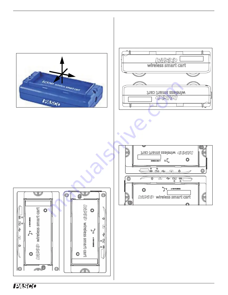
Direction of Acceleration Sensitivity

The acceleration sensing unit inside the Smart Cart is 

oriented so that the lines of greatest sensitivity follow the 

three X-Y-Z arrows indicating the direction of 

acceleration. 

In this orientation, the X-axis direction is ‘along’ the long 

axis of the Smart Cart, the Y-axis direction is 

‘perpendicular’ relative to the top of the Smart Cart. The 

Z-axis direction is ‘perpendicular’ to the long axis of the 

Smart Cart and parallel relative to the top of the cart.

Test the Smart Cart’s Output Using Earth’s Gravity

Start the PASCO Data Collection Software. If the Smart 

Cart is held so that the X-axis on the top of the Smart 

Cart is vertical and pointing upward, the Acceleration 

X-axis reading is +1.0 g. If the Smart Cart is turned so 

the X-axis is vertical but pointing downward, the 

Acceleration X-axis reading is -1.0 g (where “g” 

represents the acceleration due to gravity).

If the Smart Cart is held so that the accessory tray is on 

top and horizontal, the Acceleration Y-axis reading is 1.0 

g. If the Smart Cart is turned so that the accessory tray is 

horizontal and on the bottom, the Acceleration Y-Axis 

reading is -1.0 g. 

If the Smart Cart is placed so its side so that the Z-axis 

on the top of the cart is pointing upward, the 

Acceleration Z-axis reading is 1.0 g. If the Smart Cart is 

placed on its other side so the Z-axis is pointing down

-

ward, the Acceleration Z-axis reading is -1.0 g. 

Smart Cart Accessories

For help in deciding on accessories for the Smart Cart, 

go to

www.pasco.com/products

and select Carts and Tracks under Product Families.

Accessories Include:

Fan Accessory

Ballistic Cart Accessory

+X

+Y

+Z

+1.0 g in X

-1.0 g in X

+1.0 g in Y

-1.0 g in Y

+1.0 g in Z

-1.0 g in Z

Summary of Contents for ME-1240

Page 1: ...reedom in acceleration The Smart Cart also includes a gyroscope type sensing element that can measure rotational motion The Smart Cart can make its measurements on or off a dynamics track and transmit...

Page 2: ...the X axis in the graphic that represents the acceleration sensor s position The Smart Cart is designed to optimize the battery usage time Since each Smart Cart has a unique Device ID number more than...

Page 3: ...tion For a micro USB cable connection to a USB port For a micro USB cable connection to a USB charger Check the PASCO Web page at www pasco com software for help in selecting the right software and to...

Page 4: ...uter Zero Tare the Force Sensor At the beginning of an experiment the measurement from the built in force and acceleration sensors may not be zero when the force or acceleration is actually zero This...

Page 5: ...is 1 0 g If the Smart Cart is turned so the X axis is vertical but pointing downward the Acceleration X axis reading is 1 0 g where g represents the acceleration due to gravity If the Smart Cart is h...

Page 6: ...connect the sensor to a USB port or a USB charger Battery Usage Battery life is very important to making the product simple and always ready to use so all of the PASCO wireless products are designed...

Page 7: ...t the PASCO Web site at www pasco com manuals and enter the product number PS 3202 in the text window Replacement Parts For information about replacement parts contact Technical Support USB Cable Micr...

Page 8: ...mental laws and regulations to ensure that it will be recycled in a manner that protects human health and the environment To find out where you can drop off your waste equipment for recycling please c...

Page 9: ...s Bluetooth SMART Bluetooth SMART also known as Bluetooth Low Energy or Version 4 0 of the Bluetooth specification is the latest protocol of the proprietary open wireless technology standard created b...

Page 10: ...t In PASCO Capstone select PASCO Capstone Help from the Help menu or press F1 In PASCO Capstone there are options for setting the Wireless Force Sensor to zero One option is to use the Zero button 1 S...

Page 11: ...oint 1 click the Standard Value box and enter the known force value that is 9 8 10 Under Calibration Point 1 click Read From Sensor The value measured by the sensor is transferred to the Sensor Value...

Page 12: ...tion procedure each point is reset by associating a known standard value for instance the temperature of ice water with a raw input measurement that the sensor sends out when it is in that standard In...

Page 13: ...l Support ME 1240 Red ME 1241 Blue 13 013 14727B higher than the first probe Normally this difference would be insignificant however an offset calibration can be used to bring the sensors into closer...

Reviews: