


Bulletin 76-00 B
10
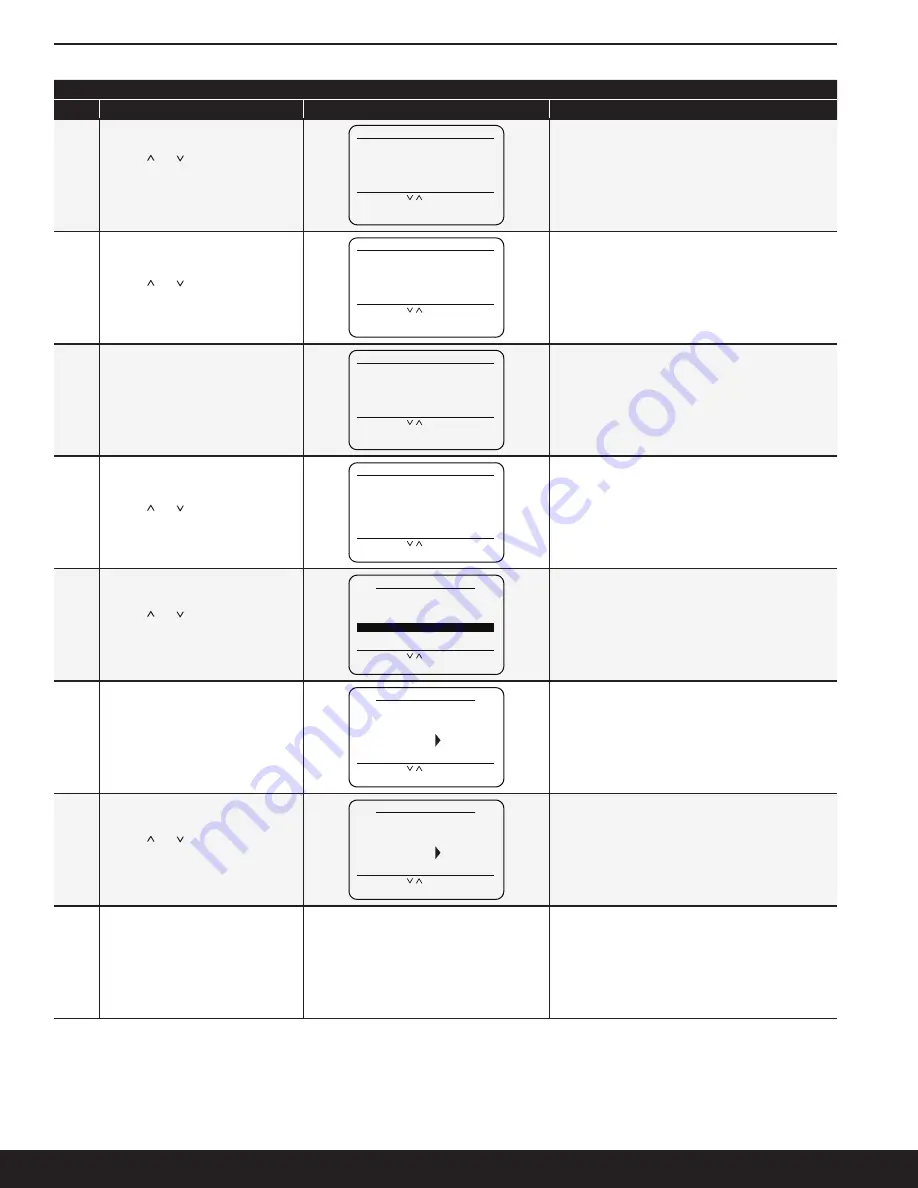
Purge Type and Points Setting Instructions
Steps
Setup Instructions
Display
Notes
10
Use the
(
∧
) or (
∨
) buttons to enter the
end time minute within the hour set in
Step 9 for the purge cycle to begin every
day
ENTER THE MINUTE: 20
SET PURGER END TIME
SELECT WITH
∨ ∧
PRESS (ENTER)
PRESS (MENU) TO GO BACK
TO SETTING START TIME
If the Purge time is set for Greenwich Mean Time (GMT),
jump to Step 11
If the Purger time is set for Military Time, jump to Step 12
11
Use the
(
∧
) or (
∨
) buttons to select the
end meridiem, 'AM' or 'PM
AUTO
SELECT AM / PM: PM
SET PURGER END TIME
SELECT WITH
∨ ∧
PRESS (ENTER)
PRESS (MENU) TO GO BACK
TO SETTING START TIME
12
This screen gives the opportunity to
check if all the values for Time-Based
purging are correct. If everything
entered is correct, press (Enter) to make
the changes
PLEASE REVIEW SETTING:
SELECT WITH
∨ ∧
PRESS (ENTER)
PRESS (MENU) TO GO BACK
TO SETTING STOP TIME
START TIME: 9:05 AM
END TIME: 11:20 PM
START / END TIME REVIEW
To cancel the operation, press (Menu) to return to the
beginning of the Stop Time setting screens
13
Use the
(
∧
) or (
∨
) buttons to select the
number of Purge Points in the system
HOW MANY POINTS ARE NEEDED?
04
SETUP POINTS
SELECT WITH
∨ ∧
PRESS (ENTER)
PRESS (MENU) TO GO BACK
14
Use the
(
∧
) or (
∨
) buttons to select
the specific purge point that needs its
Duration altered and press (Enter)
SELECT WITH
∨ ∧
PRESS (ENTER)
PRESS (MENU) TO RETURN
01
03
02
POINT
DURATION
04
20 MIN
10 MIN
15 MIN
20 MIN
15
When the purge point is selected, press
(Enter) to allow the respective duration to
be selectable
SELECT WITH
∨ ∧
PRESS (ENTER)
PRESS (MENU) TO RETURN
01
03
02
POINT
DURATION
04
20 MIN
10 MIN
15 MIN
20 MIN
The Duration options are 5 min, 10 min, 15 min,
and 20 min
16
Use the
(
∧
) or (
∨
) buttons to select the
duration of a particular purge point and
then press (Enter) to set the duration
SELECT WITH
∨ ∧
PRESS (ENTER)
PRESS (MENU) TO RETURN
01
03
02
POINT
DURATION
04
20 MIN
10 MIN
15 MIN
20 MIN
17
Repeat steps 14-16 until all the purge
points have the desired durations
Purge Type and Points Setting Instructions Continued
Summary of Contents for V300
Page 24: ...Bulletin 76 00 B 24 A A P P E N D I X...
Page 35: ...Bulletin 76 00 B 35...


