Installation of the multi-axis system PSD1-M
64 (109)
192-011006N8 2019-07
09.10.19 09:27
5.12.7.5
Mains connection Power module PSD1-M_P020 with
line choke
Increased power by means of a line choke (see page
Category
Specifications
PSD1-M_P020 with line
choke
230 V
400 V
480 V
Mains voltage
230 VAC ±10 % 50-60 Hz
400 VAC ±10 % 50-60 Hz
480VAC ±10% 50-60Hz
Rated voltage
3 AC 230 V
3 AC 400 V
3 AC 480 V
Input Current [rms]
44 A
44 A
40 A
Output voltage
325 VDC ±10 %
565 VDC ±10 %
680 VDC ±10 %
Output power
15.5 kW
27 kW
30 kW
Pulse power (<5 s)
31 kW
54 kW
60 kW
Power dissipation
140 W
140 W
140 W
Maximum fuse rating per
device
2 special purpose fuses in
line are required
Cable protection measure:
MCB (K characteristic) with a rating of 50A / 4xxVAC (depending on the input voltage)
Recommendation: (ABB) S203U-K50 (440VAC)
Device protection measure:
Circuit breakers 80A / 700VAC per supply leg in accordance with UL category JFHR2
Requirement: Bussmann 170M1366 or 170M1566D
Earth leakage current
Current on the mains PE (see page 24) (>3,5 mA)
Supply networks
Possible supply networks (see page 24): TN
The specified performance data are only valid in connection with
line choke
(see
page 87) IND-0002-01 or IND-0002-02 (UL).
5.12.8.
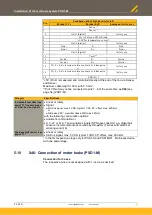
X40: Braking resistor / Temperature switch PSD1-M_P (Power supply)
The energy generated during braking operation must be dissipated via a
braking
resistor
(see page 89).
Pin
Description
+R
+ Braking resistor
short circuit proof!
-R
- Braking resistor
PE
PE
T1R
Temperature switch
T2R
Temperature switch
Device type
PSD1-M_P010
PSD1-M_P020
Capacity/ storable
energy
550 µF/
92 Ws at 400 V
53 Ws at 480 V
1175 µF/
197 Ws at 400 V
114 Ws at 480 V
Minimum braking
resistance
27
Ω
10
Ω
Recommended nominal
power rating
500 ... 1500 W
500...5000 W
Pulse power for 1s
22 kW
60 kW
Maximum permissible
continuous current
13 A
25 A
Maximum capacity in the axis system:
•
PSD1-M_P010: 2400 µF
•
PSD1-M_P020: 5000 µF
Reference value for the required capacity in an axis system


