background image

   English

1 / 8

ICEP003-005 (60Hz)

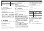
1 Safety

1.1  Importance of the manual

•  Keep it for the entire life of the machine.
•  Read it before any operation.
•  It is subject to changes: for updated information see the version on 
the machine.

1.2 Warning signals

!

Instruction for avoiding danger to persons.

Y

Instruction for avoiding damage to the equipment.

Z

The presence of a skilled or authorized technician is re-
quired.

,

There are symbols whose meaning is given in the para. 7.

1.3 Safety instructions

Every unit is equipped with an electric disconnecting switch for 

operating in safe conditions. Always use this device in order to elimi-
nate risks maintenance.

!

 The manual is intended for the end---user, only for operations 

performable with closed panels: operations requiring opening with tools 
must be carried out by skilled and qualifi ed personnel.

Y

 Do not exceed the design limits given on the dataplate.

! Y

 It is the user’s responsibility to avoid loads different

from the internal static pressure. The unitmust be appropriately
protected whenever risks of seismic phenomena exist.
Only use the unit for professional work and for its intended purpose.
The user is responsible for analysing the application aspects for prod-
uct installation, and following all the applicable industrial and safety 
standards and regulations contained in the product instruction manual 
or other documentation supplied with the unit.
Tampering or replacement of any parts by unauthorised personnel and/
or improper machine use exonerate the manufacturer from all responsi-
bility and invalidate the warranty.
The manufacturer declines and present or future liability for damage to 
persons, things and the machine, due to negligence of the operators, 
non-compliance with all the instructions given in this manual, and non-
application of current regulations regarding safety of the system.
The manufacturer declines any liability for damage due to alterations 
and/or changes to the packing.
It is the responsibility of the user to ensure that the specifi cations 
provided for the selection of the unit or components and/or options are 
fully comprehensive for the correct or foreseeable use of themachine 
itself or its components.

IMPORTANT: The manufacturer reserves the right to modify this 
manual at any time.

For the most comprehensive and updated information, the user is 
advised to consult the manual supplied with the unit.

!Y 

Access to the appliance is not permitted for the general 

public.

!Y 

Appliance is not to be used by children or persons with 

reduced physical, sensory or mental capabilities, or lack of experi-
ence and knowledge.

!Y 

Children being supervised not to play with appliance. 

!Y 

Cleaning and user maintenance shall not be made by 

children.

If the supply cord is damaged, it must be replaced by 

service agent or similarly qualifi ed persons in order to avoid a 
hazard.

If the supply cord is damaged, it must be replaced by 

service agent or similarly qualifi ed persons in order to avoid a 
hazard.

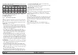
1.4 Residual risks

The installation, start up, stopping and maintenance of the machine-
must be performed in accordance with the information and instructions 
given in the technical documentation supplied and always in such a 
way to avoid the creation of a hazardous situation.
The risks that it has not been possible to eliminate in the design stage 
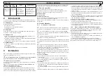
are listed in the following table.

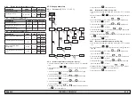
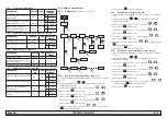
part

affected

residual

risk

manner of

exposure

precautions

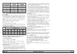
heat exchanger

coil

small cuts

contact

avoid contact, wear 
protective gloves

fan grille and

fan

lesions

insertion of pointed 
objects through the 
grille while the fan is 
in operation

do not poke objects of 
any type through the 
fan grille or place any 
objects on the grille

inside the 
unit: com-
pressor and 
discharge 
pipe

burns

contact

avoid contact, wear 
protective gloves

inside the 
unit: metal 
parts and 
electrical 
wires

intoxication, 
electrical 
shock, seri-
ous burns

defects in the 
insulation of the 
power supply lines 
upstream of the 
electrical panel; live 
metal parts

adequate electrical 
protection of the power 
supply line; ensure 
metal parts are properly 
connected to earth

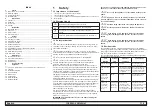
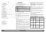
Index

1 Safety 

1

1.1  Importance of the manual ................................................................1
1.2 Warning signals ................................................................................1
1.3 Safety instructions ............................................................................1
1.4 Residual risks ...................................................................................1

2 Introduction 

2

2.1 Transport 

...........................................................................................2

2.2 Handling ...........................................................................................2
2.3 Inspection .........................................................................................2
2.4 Storage .............................................................................................2

3 Installation 

2

3.1 Operating space ...............................................................................2
3.2 Versions ............................................................................................2
3.3 Water circuit 

......................................................................................2

3.4 Electrical circuit ................................................................................3

4 Control 

4

4.1 Control panel ....................................................................................4
4.2  Starting the chiller .............................................................................4
4.3  Stopping the chiller ...........................................................................4
4.4 Parameter settings ...........................................................................4
4.5 Change parameters ..........................................................................5
4.6 Setting clock/date. ...........................................................................6
4.7  Visualization of temperature probes B1,B2  .....................................6
4.8 Alarms management 

.........................................................................6

4.9 Alarm/Warning history ......................................................................7
4.10 Automatic restart ............................................................................7

5 Maintenance 

7

5.1 General instructions 

..........................................................................7

5.2 Preventive maintenance ...................................................................7
5.3 Refrigerant ........................................................................................7
5.4 Dismantling .......................................................................................7

6 Troubleshooting 

8

7 Appendice

,

 There are symbols whose meaning is given in the par. 7.1.

7.1 Legend
7.2 Installation diagram
7.3 Technical data
7.4 Dimensions
7.5 Spare parts
7.6 Circuit diagram
7.7 Wiring diagram

Summary of Contents for Hyperchill Plus

Page 1: ...Hyperchill 60Hz EN User Manual ES Manual de uso FR Manuel d utilisation DATE 14 02 2022 Rev 8 CODE 398H271706 ICEP003 ICEP005 Plus...

Page 2: ......

Page 3: ...e appliance is not permitted for the general public Y Appliance is not to be used by children or persons with reduced physical sensory or mental capabilities or lack of experi ence and knowledge Y Chi...

Page 4: ...pump s impeller to avoid the risk of blockage when it is re started In case the impeller is blocked then you should unblock it manually Remove the rear cover of the pump and carefully turn the plasti...

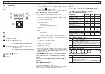
Page 5: ...current specified on the appliance data plate The chosen device must be lockable in the open position in case of maintenance Collegamento 1 The electrical power supply must be connected to the chille...

Page 6: ...l below 41 F If the temperature is too low add the appropriate quantity of glycol as explained under heading 3 3 2 Y ATTENTION before switching on the chiller pump close the water outlet valve Always...

Page 7: ...t to enter 5 Select the parameter SEt using and buttons and press the button set to enter 6 Change the value using and buttons and press the but ton set to confirm and exit 7 Press the button esc thre...

Page 8: ...2 wait for 3 seconds to see the temperature value 5 Press the button esc to exit 4 8 Alarms management see fig 1 5 Fig 5 set set 23 5 Y Y Pb Y Y AL set Er__ Er__ Y ALARM Y 1 Press the button set to st...

Page 9: ...enance make sure the power to the refrigerator is disconnected Y Always use the Manufacturer s original spare parts otherwise the Manufacturer is relieved of all liability regarding machine malfunctio...

Page 10: ...ERATURE TO BELOW THE SPECIFIED LIMIT PRESSURE SWITCH BROKEN OR WRONGLY CALIBRATED REPLACE PRESSURE SWITCH REFRIGERANT FILTER CLOGGED REPLACE THE FILTER CONDENSER FINS DIRTY CLEAN THE FINS OF THE CONDE...

Page 11: ...i n de este manual Para que la infor maci n resulte completa se recomienda al usuario consultar el manual a pie de m quina Y El acceso al aparato no est permitido para el p blico en general Y Este dis...

Page 12: ...ajo presi n se aconseja instalar una v lvula de seguridad calibrada a 6 bar Versi n por agua Y Versi n enfriada por agua Se recomienda instalar filtros de red en los tubos de entrada y salida del agua...

Page 13: ...n interruptor diferencial termomagn tico que sea adecuado para la absorci n que se especifica en la placa de datos con un hueco de contacto que permita la desconexi n total bajo condiciones de sobrete...

Page 14: ...ua tratada no cae por debajo de 41 F y que la temperatura ambiente en que funciona el circuito hidr ulico no cae por debajo de 41 F Si la temperatura es demasiado baja utilice una cantidad adecuada de...

Page 15: ...etros de tipo D 3 Seleccione el par metro PAr con los botones y y pulse el bot n set para acceder 4 Seleccione el par metro tEr con los botones y y pulse el bot n set para acceder 5 Seleccione el par...

Page 16: ...el bot n esc para salir 4 8 Gesti n de alarmas v ase fig 1 4 Fig 4 set set 23 5 Y Y Pb Y Y AL set Er__ Er__ Y ALARMA Y 1 Pulse el bot n set para encenderla 2 Alarma ON LED en rojo 3 Pulse el bot n set...

Page 17: ...r operaci n de mantenimiento contro lar que se haya cortado la alimentaci n del refrigerador Y El uso de repuestos no originales exime al fabricante de toda responsabilidad por el mal funcionamiento d...

Page 18: ...RA AMBIENTE AL CAMPO DE FUNCIONAMIENTO INDI CADO PRESOSTATO ROTO O DESCALIBRADO CAMBIAR EL PRESOSTATO FILTRO REFRIGERANTE ATASCADO SUSTITUIR EL FILTRO ALETAS DEL CONDENSADOR SUCIAS LIMPIAR LAS ALETAS...

Page 19: ...la s lec tion de l unit ou de ses composants et ou options sont parfaitement conformes pour une utilisation correcte de cette m me unit ou de ses composants ATTENTION Le fabricant se r serve le droit...

Page 20: ...3 Circuit hydraulique 3 3 1 Contr les et raccordement Y Avant de raccorder le refroidisseur et de remplir le circuit s assu rer que les tuyaux sont propres Dans le cas contraire laver soigneuse ment Y...

Page 21: ...ibution syst me TT Le conducteur de phase et le conducteur de neutre ne doivent pas tre confondus 3 Entre le c ble d alimentation et le circuit lectrique monter un inter rupteur thermomagn tique diff...

Page 22: ...p rature de l eau trait e ne descend pas sous 41 F et que la temp rature ambiante dans laquelle le circuit hydraulique fonctionne ne descend pas sous 41 F Si la temp rature est trop basse ajouter la q...

Page 23: ...et puis appuyer sur le bouton set pour entrer 6 Modifier la valeur l aide des boutons et et appuyer sur le bouton set pour confirmer et quitter 7 Appuyer trois fois sur le bouton esc pour quitter 4 5...

Page 24: ...t pour d marrer 2 Alarme ALLUM E DEL allum e rouge 3 Appuyer sur le bouton set pour entrer dans le menu et utiliser les boutons et pour s lectionner le param tre AL 4 Appuyer sur le bouton set pour af...

Page 25: ...le cas contraire le constructeur est d gag de toute responsabilit pour le mauvais fonctionnement de la machine Y En cas de fuite du r frig rant appeler un professionnel qualifi et agr par le construc...

Page 26: ...P RATURE AMBIANTE SOUS LA VALEUR LIMITE D CLAR E PRESSOSTAT CASS OU D R GL REMPLACER LE PRESSOSTAT FILTRE R FRIG RANT COLMAT REMPLACER LE FILTRE AILETTES DU CONDENSATEUR SALES NETTOYER LES AILETTES DU...

Page 27: ...Ap ndice Appendix Appendice Hyperchill 60Hz Plus ICEP003 ICEP005 DATE 14 02 2022 Rev 8 CODE 398H271706...

Page 28: ......

Page 29: ...on diagram 6 7 3 Techincal data 7 7 4 Dimensional drawings 8 Dimensional drawings Water level indicator 9 7 5 Spare parts 10 7 6 Circuit Diagram water 12 Circuit Diagram oil 13 7 7 Wiring diagram 14 W...

Page 30: ...sans pompe Peso Weight Poids Amb Temperatura ambiente Ambient temperature Temp rature ambiante Durante el transporte y el almacenamiento During transport and stockage Pendant le transport et l entrepo...

Page 31: ...ression maximum d utilisation c t air Valores de calibraci nCalibration values Valeurs de r glage 0 Cable de secci n m nima validado para la co nexi n el ctrica Minimum section validated cable for ele...

Page 32: ...ador refrigerante Refrigerant condenser Condenseur r frig rant 3 EV1 Motor del ventilador Fan motor lectroventilateur 4 Filtro refrigeranteRefrigerant filter Filtre r frig rant 5 V lvula de expansi n...

Page 33: ...ure sensor Sonde temp rature vaporateur 12 A1 Control electr nico Electronic control Contr le lectronique 13 PV Presostato Ventilator Fan pressure switch Pressostat ventilateur 14 HP1 Presostato de al...

Page 34: ...L1 Sensor de nivel de agua Water level sensor Capteur niveau eau 20 T1 Termostato de seguridad Safety thermostat Thermostat de s curit QS Interruptor seccionador g neral Main disconnector switch Inte...

Page 35: ...ater meter contatore acqua 10 2 Gauge manometro 10 3 Non return valve valvola di non ritorno 10 4 Air separator separatore d aria 10 5 Water fill hose tubo di alimentazione scollegabile 11 Antifreeze...

Page 36: ...Pressure Tempe Pressure ICEP003 1 5 barg 0 15 MPag 22 PSIg 28 barg 2 8 MPag 406 PSIg 11 4 barg 3 4 BSP F supplied with adaptors 3 4 NPT F n a 1 2 BSP F Min 5 C 41 F Max 30 C 86 F Min 0 3 bar 0 03 MPa...

Page 37: ...RLA A LRA A Kw FLA A HP Kw ICEP003 12 17 12 0 13 1 14 5 20 14 0 20 15 0 20 7 4 38 1 32 3 9 10 14 0 6 3 69 17 15 0 55 4 84 18 70 0 75 0 87 1 6 0 13 ICEP005 13 06 13 1 14 2 15 5 20 15 5 20 16 5 20 9 7...

Page 38: ...SCITA ARIA CONDENS CONDENSER AIR INLET INGRESSO ARIA CONDENS WATER CHARGE FOR OPEN CIRCUIT VERSION CARICO ACQUA PER VERSIONE A CIRCUITO APERTO BLEED VALVE FOR CLOSED CIRCUIT VERSION VALVOLA DI SFIATO...

Page 39: ...3 005 60Hz SECOND POINT OF WATER CHARGE SECONDO PUNTO DI CARICO ACQUA Range Livello acqua Water level range Circuito aperto Open circuit FiIRST POINT OF WATER CHARGE PRIMO PUNTO DI CARICO ACQUA SECOND...

Page 40: ...eat exchanger O W 17 398H473583 398H473584 6 fan kit O W 3 398H473593 refrigerant condenser O W 2 398H114842 refrigerant filter O W 4 398H206219 pump P30 3 barg W 6 398H473596 pump P50 5 barg 398H4735...

Page 41: ...5 Spare parts 12 ICEP003 005 60Hz COMPONENT Oil O Water W 7 4 7 5 ICEP003 ICEP005 FILTERS optional element W housing W element W on request housing W on request element W on request housing W on reque...

Page 42: ...A PIASTRE SONDA TEMPERATURA ANTIGELO SONDA TEMPERATURA ACQUA SERBATOIO ACQUA SFIATO VALVOLA DI SCARICO ACQUA ELECTRONIC CONTROL TEMPERATURE SENSOR ANTI FREEZE WATER TEMPERATURE SENSOR AIR HOLE WATER...

Page 43: ...OIL OUTLET TEMPERATURE SENSOR OIL MANOMETER PUMP FAN PRESSURE SWITCH HIGH PRESSURE SWITCH SCHRADER VALVE EXCHANGER CONTROLLO ELETTRONICO MANOMETRO OLIO POMPA PRESSOSTATO VENTILATORE PRESSOSTATO ALTA...

Page 44: ...7 7 Wiring diagram 15 ICEP003 005 60Hz Sheet 1 7...

Page 45: ...7 7 Wiring diagram 16 ICEP003 005 60Hz Sheet 2 7...

Page 46: ...7 7 Wiring diagram 17 ICEP003 005 60Hz Sheet 3 7...

Page 47: ...7 7 Wiring diagram 18 ICEP003 005 60Hz Sheet 4 7...

Page 48: ...7 7 Wiring diagram 19 ICEP003 005 60Hz Sheet 5 7...

Page 49: ...7 7 Wiring diagram 20 ICEP003 005 60Hz Sheet 6 7...

Page 50: ...7 7 Wiring diagram 21 ICEP003 005 60Hz Sheet 7 7...

Page 51: ......

Page 52: ......

Page 53: ......

Page 54: ...com igfg E mail gsfsupport parker com Parker Hannifin Manufacturing S r l Sede Legale Via Privata Archimede 1 2009 Corsico MI Italy Sede Operativa Gas Separation and Filtration Division EMEA Strada Zo...

Reviews: