background image

   English

2 / 8

ICEP003-005 (60Hz)

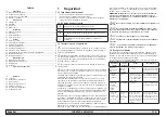
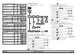
part

affected

residual

risk

manner of

exposure

precautions

outside the 
unit: area 
surrounding 
the unit

intoxica-
tion, serious 
burns

fi re due to short 
circuit or overheat-
ing of the supply 
line upstream of 
the unit’s electrical 
panel

ensure conductor 
cross-sectional areas 
and the supply line 
protection system 
conform to applicable 
regulations

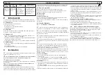
2 Introduction

The fan, pump and compressor motors are equipped with a thermal 
protector that protects them against possible overheating.

2.1 Transport

The packed unit must remain:

a)  Upright;
b)  Protected against atmospheric agents;
c)  Protected against impacts.

2.2 Handling

Use a fork-lift truck suitable for the weight to be lifted, avoiding any 
type of impact.

2.3 Inspection

a)  All the units are assembled, wired, charged with refrigerant and oil 

and tested in the factory;

b)  On receiving the machine check its condition: immediately notify 

the transport company in case of any damage; 

c)  Unpack the unit as close as possible to the place of installation.

2.4 Storage

a)  Keep the unit packed in a clean place protected from damp and 

bad weather.

b)  Do not stack the units;
c)  Follow the instructions given on the package.

3 Installation

For correct installation, follow the instructions given in par.7.2, 7.3 

and 7.7.

!


It is recommended that all chillers be fi tted with adequate pre-

fi ltration near the inlet water to the chiller.

!


Liquids to be chilled

The liquids to be chilled must be compatible with the materials used.
Examples of liquids used are water or mixtures of 

water and ethylene 

or propylene glycols or oil.

The liquids to be chilled must not be fl ammable. 
If the liquids to be chilled contain hazardous substances (e.g. ethylene/
propylene glycol), any liquid discharged from a leakage area must be 
collected, because it is harmful to the environment.  When draining 
the hydraulic circuit, comply with the current regulations and do not 
disperse the contents in the environment.

3.1 Operating space

Leave a space of 1.5 m around the unit. 
Leave a space of at least 2 metres above the refrigerator in models with 
vertical emission of condensation air.

3.2 Versions

Axial fans (A)

Do not create cooling air recirculation situations. 
Do not obstruct the ventilation grilles.
The ducting of extracted air is not recommended for versions with axial 
fans.

3.3 Water circuit

3.3.1 

Checks and connection

Before connecting the chiller and fi lling the circuit, check that all 

the pipes are clean. If not, wash them out thoroughly.

If the plumbing circuit is of the closed type (only for ICEP005), 

under pressure it is advisable to install a safety valve set to:
6 bar (for water version) 

(for water version) Always install mesh fi lters on the water inlet and 

outlet pipelines.

If the hydraulic circuit is intercepted by automatic valves, protect 

the pump with an anti-hammering system.

(for water version) If the hydraulic circuit is emptied for shut-down 

periods we recommend that you add lubricating fl uid to the pump’s 
impeller to avoid the risk of blockage when it is re-started. In case the 
impeller is blocked then you should unblock it manually.
Remove the rear cover of the pump and carefully turn the plastic fan. 
If the impeller is stuck then remove the fan and turn the impeller shaft 
directly. After un-blocking the impeller re-assemble the fan and cover.

Preliminary checks

1)  Check that any shut-off valves in the idraulic circuit are open.
2)  (for water version) In the case of a closed water circuit(only for 

ICEP005), check that an expansion tank of suitable capacity has 
been installed. See paragraph 3.3.3.

Connection

1)  Connect the cooler to the inlet and outlet piping, using the special 

connections located on the back of the unit.
We recommend the use of fl exible unions to reduce system rigidity.

2)  (for water version) Fill the water circuit using the fi tting provided on 

the rear of the chiller (

).

3)  (for water version) The tank is equipped with a breather valve 

that should be operated manually when fi lling the tank. Also, if the 
hydraulic circuit has high points, install a vent valve at the highest 
points.

4)  We recommend that taps are installed on the inlet and outlet pipes, 

so that the unit can be excluded for maintenance when necessary.

5)  If the chiller works with an open tank, the pump must be installed 

on intake to the tank and on delivery to the chiller.

Subsequent checks

1)  (for water version) Check that the tank and the circuit are complete-

ly full of water and that all the air has been expelled from the system.

2)  (for water version) The water circuit must always be kept full. For 

this reason, carry out periodic checks and top the circuit up if neces-
sary, or install an automatic fi lling kit.

3.3.2 

Water and ethylene glycol (water version)

If installed outdoors or in an unheated indoor area, it is possible that 
the water in the circuit may freeze if the system is not in operation dur-
ing the coldest times of the year.
To avoid this hazard:

a)  Equip the chiller with suitable antifreeze protection devices, avail-

able from the manufacturer as optional accessories;

b)  Drain the system via the drain valve if the chiller is to remain idle for 

a prolonged period;

c)  Add an appropriate quantity of antifreeze to the water in circulation 

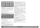
(see table).

Sometimes the temperature of the outlet water is so low as to require 
the addition of ethylene glycol in the following percentages.

Outlet water

temperature  [°C]

Ethylene glycol

(% vol.)

Ambient

temperature

4

5

-2

2

10

-5

0

15

-7

-2

20

-10

-4

25

-12

-6

30

-15

3.3.3 

Expansion tank (water version, only for ICEP005)

To avoid the possibility of an increase or decrease in the volume of the 
fl uid due to a signifi cant change in its temperature causing damage to 
the machine or the water circuit, we recommend installing an expansion 
tank of suitable capacity.
The expansion tank must be installed on intake to the pump on the rear 
connection of the tank.
The minimum volume of an expansion tank to be installed on a closed 
circuit can be calculated using the following formula:
V=2 x Vtot x (Pt min - P t max)
where
Vtot= vol. circuit total (in litres)
P t min/max= specifi c weight at the minimum/maximum temperature 
reached by the water [kg/dm3].

Summary of Contents for Hyperchill Plus

Page 1: ...Hyperchill 60Hz EN User Manual ES Manual de uso FR Manuel d utilisation DATE 14 02 2022 Rev 8 CODE 398H271706 ICEP003 ICEP005 Plus...

Page 2: ......

Page 3: ...e appliance is not permitted for the general public Y Appliance is not to be used by children or persons with reduced physical sensory or mental capabilities or lack of experi ence and knowledge Y Chi...

Page 4: ...pump s impeller to avoid the risk of blockage when it is re started In case the impeller is blocked then you should unblock it manually Remove the rear cover of the pump and carefully turn the plasti...

Page 5: ...current specified on the appliance data plate The chosen device must be lockable in the open position in case of maintenance Collegamento 1 The electrical power supply must be connected to the chille...

Page 6: ...l below 41 F If the temperature is too low add the appropriate quantity of glycol as explained under heading 3 3 2 Y ATTENTION before switching on the chiller pump close the water outlet valve Always...

Page 7: ...t to enter 5 Select the parameter SEt using and buttons and press the button set to enter 6 Change the value using and buttons and press the but ton set to confirm and exit 7 Press the button esc thre...

Page 8: ...2 wait for 3 seconds to see the temperature value 5 Press the button esc to exit 4 8 Alarms management see fig 1 5 Fig 5 set set 23 5 Y Y Pb Y Y AL set Er__ Er__ Y ALARM Y 1 Press the button set to st...

Page 9: ...enance make sure the power to the refrigerator is disconnected Y Always use the Manufacturer s original spare parts otherwise the Manufacturer is relieved of all liability regarding machine malfunctio...

Page 10: ...ERATURE TO BELOW THE SPECIFIED LIMIT PRESSURE SWITCH BROKEN OR WRONGLY CALIBRATED REPLACE PRESSURE SWITCH REFRIGERANT FILTER CLOGGED REPLACE THE FILTER CONDENSER FINS DIRTY CLEAN THE FINS OF THE CONDE...

Page 11: ...i n de este manual Para que la infor maci n resulte completa se recomienda al usuario consultar el manual a pie de m quina Y El acceso al aparato no est permitido para el p blico en general Y Este dis...

Page 12: ...ajo presi n se aconseja instalar una v lvula de seguridad calibrada a 6 bar Versi n por agua Y Versi n enfriada por agua Se recomienda instalar filtros de red en los tubos de entrada y salida del agua...

Page 13: ...n interruptor diferencial termomagn tico que sea adecuado para la absorci n que se especifica en la placa de datos con un hueco de contacto que permita la desconexi n total bajo condiciones de sobrete...

Page 14: ...ua tratada no cae por debajo de 41 F y que la temperatura ambiente en que funciona el circuito hidr ulico no cae por debajo de 41 F Si la temperatura es demasiado baja utilice una cantidad adecuada de...

Page 15: ...etros de tipo D 3 Seleccione el par metro PAr con los botones y y pulse el bot n set para acceder 4 Seleccione el par metro tEr con los botones y y pulse el bot n set para acceder 5 Seleccione el par...

Page 16: ...el bot n esc para salir 4 8 Gesti n de alarmas v ase fig 1 4 Fig 4 set set 23 5 Y Y Pb Y Y AL set Er__ Er__ Y ALARMA Y 1 Pulse el bot n set para encenderla 2 Alarma ON LED en rojo 3 Pulse el bot n set...

Page 17: ...r operaci n de mantenimiento contro lar que se haya cortado la alimentaci n del refrigerador Y El uso de repuestos no originales exime al fabricante de toda responsabilidad por el mal funcionamiento d...

Page 18: ...RA AMBIENTE AL CAMPO DE FUNCIONAMIENTO INDI CADO PRESOSTATO ROTO O DESCALIBRADO CAMBIAR EL PRESOSTATO FILTRO REFRIGERANTE ATASCADO SUSTITUIR EL FILTRO ALETAS DEL CONDENSADOR SUCIAS LIMPIAR LAS ALETAS...

Page 19: ...la s lec tion de l unit ou de ses composants et ou options sont parfaitement conformes pour une utilisation correcte de cette m me unit ou de ses composants ATTENTION Le fabricant se r serve le droit...

Page 20: ...3 Circuit hydraulique 3 3 1 Contr les et raccordement Y Avant de raccorder le refroidisseur et de remplir le circuit s assu rer que les tuyaux sont propres Dans le cas contraire laver soigneuse ment Y...

Page 21: ...ibution syst me TT Le conducteur de phase et le conducteur de neutre ne doivent pas tre confondus 3 Entre le c ble d alimentation et le circuit lectrique monter un inter rupteur thermomagn tique diff...

Page 22: ...p rature de l eau trait e ne descend pas sous 41 F et que la temp rature ambiante dans laquelle le circuit hydraulique fonctionne ne descend pas sous 41 F Si la temp rature est trop basse ajouter la q...

Page 23: ...et puis appuyer sur le bouton set pour entrer 6 Modifier la valeur l aide des boutons et et appuyer sur le bouton set pour confirmer et quitter 7 Appuyer trois fois sur le bouton esc pour quitter 4 5...

Page 24: ...t pour d marrer 2 Alarme ALLUM E DEL allum e rouge 3 Appuyer sur le bouton set pour entrer dans le menu et utiliser les boutons et pour s lectionner le param tre AL 4 Appuyer sur le bouton set pour af...

Page 25: ...le cas contraire le constructeur est d gag de toute responsabilit pour le mauvais fonctionnement de la machine Y En cas de fuite du r frig rant appeler un professionnel qualifi et agr par le construc...

Page 26: ...P RATURE AMBIANTE SOUS LA VALEUR LIMITE D CLAR E PRESSOSTAT CASS OU D R GL REMPLACER LE PRESSOSTAT FILTRE R FRIG RANT COLMAT REMPLACER LE FILTRE AILETTES DU CONDENSATEUR SALES NETTOYER LES AILETTES DU...

Page 27: ...Ap ndice Appendix Appendice Hyperchill 60Hz Plus ICEP003 ICEP005 DATE 14 02 2022 Rev 8 CODE 398H271706...

Page 28: ......

Page 29: ...on diagram 6 7 3 Techincal data 7 7 4 Dimensional drawings 8 Dimensional drawings Water level indicator 9 7 5 Spare parts 10 7 6 Circuit Diagram water 12 Circuit Diagram oil 13 7 7 Wiring diagram 14 W...

Page 30: ...sans pompe Peso Weight Poids Amb Temperatura ambiente Ambient temperature Temp rature ambiante Durante el transporte y el almacenamiento During transport and stockage Pendant le transport et l entrepo...

Page 31: ...ression maximum d utilisation c t air Valores de calibraci nCalibration values Valeurs de r glage 0 Cable de secci n m nima validado para la co nexi n el ctrica Minimum section validated cable for ele...

Page 32: ...ador refrigerante Refrigerant condenser Condenseur r frig rant 3 EV1 Motor del ventilador Fan motor lectroventilateur 4 Filtro refrigeranteRefrigerant filter Filtre r frig rant 5 V lvula de expansi n...

Page 33: ...ure sensor Sonde temp rature vaporateur 12 A1 Control electr nico Electronic control Contr le lectronique 13 PV Presostato Ventilator Fan pressure switch Pressostat ventilateur 14 HP1 Presostato de al...

Page 34: ...L1 Sensor de nivel de agua Water level sensor Capteur niveau eau 20 T1 Termostato de seguridad Safety thermostat Thermostat de s curit QS Interruptor seccionador g neral Main disconnector switch Inte...

Page 35: ...ater meter contatore acqua 10 2 Gauge manometro 10 3 Non return valve valvola di non ritorno 10 4 Air separator separatore d aria 10 5 Water fill hose tubo di alimentazione scollegabile 11 Antifreeze...

Page 36: ...Pressure Tempe Pressure ICEP003 1 5 barg 0 15 MPag 22 PSIg 28 barg 2 8 MPag 406 PSIg 11 4 barg 3 4 BSP F supplied with adaptors 3 4 NPT F n a 1 2 BSP F Min 5 C 41 F Max 30 C 86 F Min 0 3 bar 0 03 MPa...

Page 37: ...RLA A LRA A Kw FLA A HP Kw ICEP003 12 17 12 0 13 1 14 5 20 14 0 20 15 0 20 7 4 38 1 32 3 9 10 14 0 6 3 69 17 15 0 55 4 84 18 70 0 75 0 87 1 6 0 13 ICEP005 13 06 13 1 14 2 15 5 20 15 5 20 16 5 20 9 7...

Page 38: ...SCITA ARIA CONDENS CONDENSER AIR INLET INGRESSO ARIA CONDENS WATER CHARGE FOR OPEN CIRCUIT VERSION CARICO ACQUA PER VERSIONE A CIRCUITO APERTO BLEED VALVE FOR CLOSED CIRCUIT VERSION VALVOLA DI SFIATO...

Page 39: ...3 005 60Hz SECOND POINT OF WATER CHARGE SECONDO PUNTO DI CARICO ACQUA Range Livello acqua Water level range Circuito aperto Open circuit FiIRST POINT OF WATER CHARGE PRIMO PUNTO DI CARICO ACQUA SECOND...

Page 40: ...eat exchanger O W 17 398H473583 398H473584 6 fan kit O W 3 398H473593 refrigerant condenser O W 2 398H114842 refrigerant filter O W 4 398H206219 pump P30 3 barg W 6 398H473596 pump P50 5 barg 398H4735...

Page 41: ...5 Spare parts 12 ICEP003 005 60Hz COMPONENT Oil O Water W 7 4 7 5 ICEP003 ICEP005 FILTERS optional element W housing W element W on request housing W on request element W on request housing W on reque...

Page 42: ...A PIASTRE SONDA TEMPERATURA ANTIGELO SONDA TEMPERATURA ACQUA SERBATOIO ACQUA SFIATO VALVOLA DI SCARICO ACQUA ELECTRONIC CONTROL TEMPERATURE SENSOR ANTI FREEZE WATER TEMPERATURE SENSOR AIR HOLE WATER...

Page 43: ...OIL OUTLET TEMPERATURE SENSOR OIL MANOMETER PUMP FAN PRESSURE SWITCH HIGH PRESSURE SWITCH SCHRADER VALVE EXCHANGER CONTROLLO ELETTRONICO MANOMETRO OLIO POMPA PRESSOSTATO VENTILATORE PRESSOSTATO ALTA...

Page 44: ...7 7 Wiring diagram 15 ICEP003 005 60Hz Sheet 1 7...

Page 45: ...7 7 Wiring diagram 16 ICEP003 005 60Hz Sheet 2 7...

Page 46: ...7 7 Wiring diagram 17 ICEP003 005 60Hz Sheet 3 7...

Page 47: ...7 7 Wiring diagram 18 ICEP003 005 60Hz Sheet 4 7...

Page 48: ...7 7 Wiring diagram 19 ICEP003 005 60Hz Sheet 5 7...

Page 49: ...7 7 Wiring diagram 20 ICEP003 005 60Hz Sheet 6 7...

Page 50: ...7 7 Wiring diagram 21 ICEP003 005 60Hz Sheet 7 7...

Page 51: ......

Page 52: ......

Page 53: ......

Page 54: ...com igfg E mail gsfsupport parker com Parker Hannifin Manufacturing S r l Sede Legale Via Privata Archimede 1 2009 Corsico MI Italy Sede Operativa Gas Separation and Filtration Division EMEA Strada Zo...

Reviews: