


Service Manual
HTG Series Integrated Hydrostatic Transmission
18
Parker Hannifin Corporation
Hydraulic Pump/Motor Division
Greeneville, Tennessee USA
HY13-1524-002-M1/US
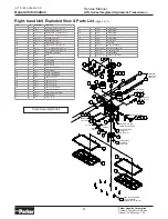
General Information
Right-hand Unit Exploded View & Parts List
(page 1 of 4)
55A
55B
4
2
5
8
8
9
1
4X
4X
2X
2X
5X
10X
2X
11
10A
28
44C
TRUNNION
ARM
TRUNNION
ARM
MOTOR
RTN SCREW
RTN SCREW
BYPASS
VALVE
BYPASS
VALVE
MOTOR
44D
44A
46
13
7
44E 12
3
44B
46
13
6
47A
47D
47B
47C
56A
56B
50
52B
52A
52D
52C
53B
53A
37A
37B
43B
43A
20A 21B
20C 21A
20B
21A
22B
24
25
22A
23
22B 24 25
22A 23
57
38
SEE PARTS LIST FOR
ORFICE PLUG OPTIONS
38
TORQUE TO
55-70 ft-lbs
26
TORQUE TO
100-120 in-lbs
TORQUE TO
200-240 in-lbs
41
TORQUE TO
115-135 in-lbs
(1/4-20 SOCKET HEAD CAP SCREW)
TORQUE TO 150-180 in-lbs
(5/16-24 SOCKET HEAD CAP SCREW)
TORQUE TO 22-24 ft-lbs
(5/16-24 SOCKET HEAD CAP SCREW)
TORQUE: 90-110 in-lbs
THRU COVER & GASKET
TO TOP HOUSING
TORQUE TO 100-120 in-lbs
TO END BLOCK
TORQUE TO
90-110 in-lbs
TO TOP HOUSING
TORQUE TO
270-300 in-lbs
TO MOTOR
TORQUE TO
45-55 ft-lbs
THRU BRAKE ASSEMBLY
TO MOTOR HOUSING
TORQUE TO 25-28 ft-lbs
TORQUE TO
21-24 ft-lbs
TORQUE TO
21-24 ft-lbs
TORQUE TO
90-110 in-lbs
TORQUE TO
90-110 in-lbs
42
16
58
17
4X 14
34
29 30 31
60
45
51
32
59
49
19
35
15
48 39 40 33
2X
18A
27
36A
54
61A
61B
61C
THRU TOP HOUSING
THRU FILTER
TUBE BRACKET
THRU
WASHER
THRU TOP
HOUSING
TO END
BLOCK
TO FILTER
10B
TORQUE TO 200 ft-lbs MIN.
+ ROTATION TO ALIGN
FOR COTTER PIN INSTALLATION
18B
36B
(TRUNNION ARM
SEAL - PN 478087)
(TRUNNION ARM
SEAL - PN 478087)
TORQUE TO 200 ft-lbs MIN.
Full view.
See additional pages
for scaled-up views
and part listings
NOTE
ITEM
QTY
PART NUMBER
DESCRIPTION
1
4
020207
FLANGE HEAD CAP SCREW, 5/16-18 UNC-3A X .75
2
4
020297
SOCKET HEAD CAP SCREW, 3/8-16 UNRC-3A X 1.5
3
1
020310
BUTTON HEAD CAP SCREW, 1/4-20 X .75
4
2
021291
SPECIAL BOLT, 3/8-24 UNF-2A X 5.375
5
2
021393
SPECIAL BOLT, 3/8-24 UNF-2A X 6.625
6
1
021485
SOCKET HEAD CAP SCREW 5/16-24 UNF-3A X .735
7
1
022006
SOCKET HEAD CAP SCREW, M8 X 1.25 X 25mm
8
15
023002
THREAD FORMING SCREW, 1/4-20 X .625
9
2
100000031-105
HEX HEAD SCREW, 1/4-28 UNRF-2A X 2.25
10A
1
025113
NUT 1-20 UNEF-2B
10B
1
025126
NUT 1-20 UNEF-2B
11
1
025164
NUT 5/8-18 UNF-2B
12
1
028022
WASHER, FLAT, Ø.259 ID X Ø.500 OD X .062
13
1
028025
WASHER, FLAT, Ø8.74mm ID X Ø17.50mm OD X 1.664mm
14
4
028996
WASHER, FLAT, Ø.406 ID X Ø.827 OD X .098
15
1
030049
LABEL
16
1
032202-013
PREFORMED O-RING SEAL
17
2
032202-116
PREFORMED O-RING SEAL
18A
1
034008
GASKET, BOTTOM COVER, FE
18B
1
034007
GASKET, BOTTOM COVER, COMPOSITE
19
1
034009
GASKET, SIDE COVER, FE
20A
1
035007
FITTING, BEADED HOSE BARB, SAE STR THD 3/4-16
20B
1
035008
FITTING, BEADED HOSE BARB, SAE STR THD 3/4-16
20C
1
035009
FITTING, 45° BEADED HOSE BARB, SAE STR THD 3/4-16
21A
1
036321
PLUG,RUBBER, Ø.594 NOM
21B
1
036326
PLUG, RUBBER, Ø.438 NOM
22A
2
036038
PLUG & O-RING ASSEMBLY, M18 X 1.5-6g
22B
2
409035
PLUG & O-RING ASSEMBLY, M18 X 1.5-6g
23
2
410113
RELIEF VALVE SUB-ASSEMBLY
24
2
401143
SPRING
25
2
409041
POPPET VALVE
26
1
036044
HOLLOW HEX VENT PLUG ASSEMBLY, 3/4-16 UNF-2A
27
1
038016
WOODRUFF KEY 5/16 X 1
28
1
040204
COTTER PIN
29
1
063048
THRUST BEARING
30
1
069010
THRUST WASHER
31
1
069011
THRUST WASHER
32
1
401114
INTERNAL RETAINING RING (SHAFT SEAL)
33
1
401145
EXTERNAL RETAINING RING
34
1
401302
SPRING (CENTRAL)
35
1
402132
SIDE COVER
36A
1
402136
BOTTOM COVER ASSEMBLY
36B
1
402139
BOTTOM COVER ASSEMBLY
37A
1
403855
PULLEY, Ø6.50 NOM, TAPERED HUB
37B
1
403856
PULLEY, Ø5.00 NOM, TAPERED HUB
38A
2
409353
ORIFICE PLUG (Ø .018)
38B
2
409354
ORIFICE PLUG (Ø .024)
38C
2
409355
ORIFICE PLUG (Ø .031)
38D
2
409356
ORIFICE PLUG (Ø .044)
38E
2
409357
ORIFICE PLUG (NO ORIFICE)
39
1
410123
BYPASS VALVE ASSEMBLY
40
1
410124
CHARGE RELIEF VALVE ASSEMBLY
41
1
411135
FILTER ASSEMBLY
42
1
411137
FILTER TUBE (RH)
43A
1
420067
FAN, Ø8.3
43B
1
420142
FAN, Ø7.8
44A
1
420068
ROTATING BRACKET
44B
1
420073
ROTATING BRACKET (RH)
44C
1
420078
RTN ASSEMBLY (RH)
44D
1
420123
RTN ASSEMBLY (RH)
44E
1
452028
ROTATING BRACKET
45
1
452011
CONTROL BLOCK
46
1
452020
TRUNNION BLOCK
47A
1
452005
TRUNNION ARM
47B
1
452016
TRUNNION ARM
47C
1
452019
TRUNNION ARM
47D
1
452027
TRUNNION ARM
48
1
452018
BYPASS LEVER
49
1
477370
FAN SPACER
50
1
477369
PORT PLATE
51
1
478086
SHAFT SEAL
52A
1
490164
BRAKE ASSEMBLY
52B
1
490169
BRAKE ASSEMBLY
52C
1
490225
BRAKE ASSEMBLY
52D
1
490242
BRAKE ASSEMBLY
53A
1
490216
BRAKE DRUM, 5 BOLT
53B
1
490218
BRAKE DRUM, 4 BOLT
54
1
H1A014000
ROTOR SET ASSEMBLY
55A
1
H1A147000
PISTON & BARREL ASSEMBLY, 14cc/REV
55B
1
H1A167000
PISTON & BARREL ASSEMBLY, 16cc/REV
56A
1
HD012001R-A1
TOP HOUSING ASSEMBLY (RH)
56B
1
HD012001R-A2
TOP HOUSING ASSEMBLY (RH)
57
1
HD016000R-A1
END BLOCK ASSEMBLY (RH)
58
1
HD018000
CHARGE PUMP COVER
59
1
HD019000-A1
SHAFT ASSEMBLY
60
1
HP2013000-A1
SWASH BLOCK ASSEMBLY
61A
1
TG0240SD081HTAA MOTOR ASSEMBLY, 240cc/REV
61B
1
TG0280SD081HTAA MOTOR ASSEMBLY, 280cc/REV
61C
1
TG0310SD081HTAA MOTOR ASSEMBLY, 310cc/REV
62
0.72gal 045642
PARKER HT-1000 HYDRAULIC TRANSMISSION OIL


