Parker Hannifin S.p.A. – S.B.C. Division
quick installation guide Hi-drive
Page 7 of 12
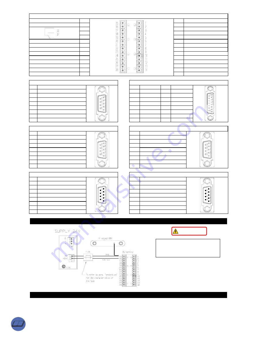
X5 : terminal connection
0VQ drive supply
15
1
– SR drive enabling
+24V drive supply
16
2
+ SR drive enabling
17 3
SC
B
18 4
SC
A
19 5
N.C.
GND (DIGITAL)
20
6
0VA
OUT 1
21
7
MON 2
OUT 0
22
8
MON 1
VCC (DIGITAL)
23
9
0VA
GND IN
24
10
– AX
IN 3 (ENCODER IN)
25
11
+ AX
IN 2 (ENCODER IN)
26
12
0VA
IN 1
27
13
– REF
IN 0
28
14 +
REF
X6 : “resolver” (DB9 female)
X7 : “sincos” (DB15 female)
1
PTC -
1
PTC -
10
Ve
2
A GND
2
SHIELD
11
SENSE -
3
ECC -
3
A GND
12
CLK -
4
SIN -
4
SENSE +
13
DATA -
5
COS -
5
CLK +
14
B -
6
PTC +
6
DATA +
15
A -
7
ECC +
7
B +
8
SIN +
8
A +
9 COS
+
9 PTC
+
X8 : “RS422/485” (DB9 female)
X9 : “encoder input” (DB9 female)
1
TX422 +
1
EIN A +
2
RX422 +
2
EIN A -
3
TX422 -
3
EIN B +
4
RX422 -
4
EIN B -
5
SHIELD
5
EIN C +
6
Termination
6
EIN C -
7 N.C.
7 0VF
8 N.C.
8 SHIELD
9 0V
F
9 +5V
F
X10 : “encoder output” (DB9 male)
X11 : “CAN” (DB9 male)
1
EOUT A +
1
N.C.
2 EOUT
A
-
2 CANL
3
EOUT B +
3
GND CAN
4 EOUT
B
-
4 Reserved
5 EOUT
C
+
5 SHIELD
6 EOUT
C
-
6 Reserved
7 0VF
7 CANH
8 Reserved
8 N.C.
9 Reserved
9 Reserved
4
24V= SUPPLY
5
CONNECTION TO POWER MAINS
Two modes that can be selected with Pr39.0:
- programme
0
for three-phase mains supply 180V~ MIN to 528V~ MAX or single-phase at 305V~ MAX.
- programme
1
for D.C. supply - 254V= MIN to 744V= MAX. Enter value in Pr21, save, switch off and then
back on.
Æ
A third possibility exists - low-voltage supply (see Operator's Manual).
With both the D.C. and the A.C. supply, the
undervoltage
threshold is set not below 70% of VMIN (254V= or
180V~). If the bit b39.8 is set at one, upon the return of the mains voltage, the undervoltage alarm is
automatically reset.
I
I
M
M
P
P
O
O
R
R
T
T
A
A
N
N
T
T
The 24 V powers the drive
electronics and therefore
controls drive switch on and off.


