


HY28-2668-01/GC/NA,EU
GOLD CUP
®
Series - Application Manual
Piston Pumps & Motors
1.4
Parker Hannifin Corporation
Hydraulic Pump Division
Marysville, Ohio USA
Section 1
Upward motion of the servo shoe with respect to the servo plate, opens the top hole of the
servo plate to servo pressure and the bottom hole of the servo plate to case pressure. Servo
pressure is then carried through the channels in the servo stem and rocker cam to the vane
chamber below the vane actuator, while the upper vane chamber is opened to case pressure.
The pressure differential establishes an upward force on the stroking vane and the rocker
cam cradle rotates upward. The servo plate and stem traveling with the rocker cam also move
upward until the holes in the servo plate are covered over by the lands on the servo shoe.
With the holes covered up, there is no longer a pressure difference across the vane actuator
and the rocker cam stops its rotation.
The servo shoe is configured such that it will store the full error signal. (i.e., rotary servo input
at full displacement in one direction while the rocker cam is at full displacement in the other
direction.)
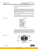
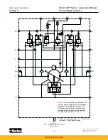
There are four servo shoes in each pump. One shoe (inside shoe on the control side) pro-
vides the 4-way valve action, the outer shoe on the control side serves to feed servo pressure
from the side plate to the inside shoe, while the other two shoes provide balancing forces
to counteract loading on the servo link assemblies and rocker cam assembly. The servo link
assembly on the control side is free to move and controls pump displacement. The servo link
assembly on the other side of the pump is restrained by the heads of the socket head cap
screws holding the servo stem and plate assembly to the rocker cam and therefore moves
with the rocker cam during displacement changes. This side forms the displacement indicator.
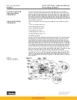
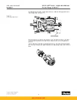
Figure 1.7
GOLD CUP
®
pump internal
configuration rotary servo input and
displacement indicator
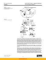
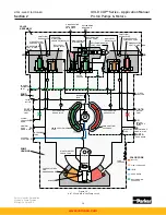
Figure 1.8
Control cover - rotary servo input
www.comoso.com


