


HY28-2668-01/GC/NA,EU
GOLD CUP
®
Series - Application Manual
Piston Pumps & Motors
ii
Parker Hannifin Corporation
Hydraulic Pump Division
Marysville, Ohio USA
Introduction
A reference text on the design & application
of the GOLD CUP
®
line of Hydrostatic transmissions pumps & motors
The GOLD CUP
®
pump has four key features which set it apart and ahead of other hydro-
static pumps.
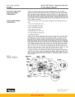
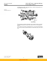
The first of these key features is the rocker cam and cradle assembly which provides for the
variable displacement. The piston rotating group rides on the rocker cam. The cam and cradle
assembly uses hydrostatic balance which provide a smooth displacement change, instead of
relying on roller bearings or trunnions, which tend to transmit noise. The combination of the
rigidity of the cam and cradle in addition to the hydraulic balance and lack of roller bearings
provide lowest noise levels and hysteresis currently available. Position of the cam is accom-
plished by two stroking vanes which are mounted on either side of the cam and cradle as-
sembly. The pressure loaded assemblies are part of the cam and provide a very direct precise
means of controlling pump displacement. The lack of any mechanical linkages to a stroking
piston eliminates mechanical wear and stress which can cause slow response, control degra-
dation, or failure.
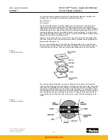
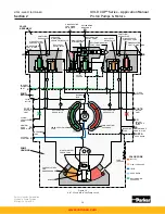
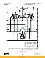
The second key feature is the unique servo control system. From the output of the servo
pump thru the rotary servo control to the vane chamber, the control system provides a reliable
control that compensates for change in system pressure and responds to changes in the input
command almost instantly. When the displacement of the pump matches the command of
the rotary servo, the control fluid is trapped in the vane chambers. Because of the compact
size, the volume of the trapped fluid is very small and is very stable. As the command signal
is changed, the pressure balanced rotary servo opens one set of vane chambers to the pump
case, while directing servo oil to the other set of vane chambers. As the cradle moves to the
position commanded by the rotary servo, the vane ports which are connected to the cradle
assembly provide the feedback to once again block the servo passages in and out of the vane
chamber. The pressure balance of the rotary servo stem insures that only minimal torque is
required for the input signal. The close tolerance between the vane chamber ports and the
servo stem insures that any error signal is instantly corrected. The servo stem is controlled by
an external signal to the servo shaft providing an input command through an arc of +19° to
-19°. Additional controls are readily available and are discussed in further detail later.
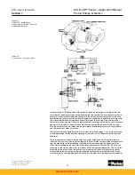
The third key feature is the servo pressure control. The servo pressure is determined by the
servo relief valve. Since replenishing oil is first directed to the servo system, total control is
always insured. A pressure modulating pin causes the servo pressure to increase as the
system pressure increases at a rate of 40 psi, 2,8 bar servo pressure per 1000 psi, 69 bar
system pressure. This increase in servo pressure adds to the rigidity of the servo system as
the pump experiences increasing load.
The fourth key feature is the large barrel bearing. This bearing absorbs the mechanical imbal-
ance caused by the forces of the pistons against the angled cam assembly. Thus the barrel is
held squarely against the port plate eliminating the possibility of barrel “tipping” or separating
from the port plate. This design eliminates the need for a large shaft bearing and consequent-
ly reduces the size of the bore circle.
The resulting component designs proved to be a unique approach in the areas of displace-
ment control mechanisms and control circuits. This manual is an attempt to convey an under-
standing of these concepts and mechanisms to the design engineering personnel who will be
using this equipment in the design of new machinery. This manual, therefore, assumes a level
of understanding of hydrostatic transmissions and hydraulic circuitry and does not attempt to
explain basic concepts.
The information contained in this manual is intended to be supplemented by specific detailed
information contained in sales brochures and service brochures.
INTRODUCTION
www.comoso.com


