


HY28-2668-01/GC/NA,EU
GOLD CUP
®
Series - Application Manual
Piston Pumps & Motors
2.2
Parker Hannifin Corporation
Hydraulic Pump Division
Marysville, Ohio USA
Section 2
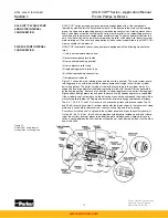
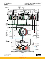
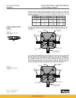
With the plug installed as shown in Figure 2.2, servo flow must be externally plumbed
between the two filter ports. This allows filtering of the servo oil before it reaches the replen-
ishing gallery. Consult installation drawings or sales bulletins for port locations. However, not
all of the servo oil is filtered. Servo oil flowing to the rotary servo on the “B” port side is not fil-
tered. If the rotary servo control is on the “A” port side, servo flow to the rotary servo is filtered.
In the 24 and 30 in
3
/rev pumps (Figure 2.4), servo pump output is directed to port G, where a
customer supplied filter, filters all servo oil. Excess servo oil spills over the servo relief valve
and into the replenishing gallery.
In the 11 and 14 in
3
/rev pumps (Figure 2.3), the servo pressure oil is not filtered. In these
pumps, the oil is filtered at replenishing pressure.
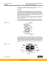
Replenishing flow is supplied by both the servo pump and replenishing pump. Excess servo
flow from the servo pump spills over the servo relief valve and into the replenishing gallery
where it joins the flow from the replenishing pump. The combined flow from the two sources is
then fed to the replenishing checks and the replenishing relief. If the optional plug is inserted
into the replenishing gallery it blocks the flow before it reaches the replenishing checks. When
the plug is installed, the replenishing flow
must
be externally plumbed. See installation draw-
ings or the sales bulletins for port locations.
Replenishing pressure in all pumps is controlled by the replenishing relief valve, which is in
turn controlled by the replenishing relief pilot stage. Replenishing pressure is exposed to the
annular area of the replenishing relief valve as shown. When replenishing pressure exceeds
the pressure set into the relief pilot stage, the pilot opens, allowing a flow from the top of the
replenishing relief valve which creates a pressure drop created through the orifice leading to
the top of the valve from the replenishing gallery. The valve then opens and controls the pres-
sure in the replenishing gallery. A small filter screen between the replenishing relief poppet
and pilot section prevents the pilot from becoming stuck from contamination. Excess replen-
ishing flow is spilled into the light blue area and is carried through a passage near the port
plate in the port block before it spills into the case of the pump. This flow cools the port plate
to cylinder barrel interface during idle. Internal leakage from the rotating group and output
control flow from the manual rotary servo, join the excess replenishing flow in the case and all
are carried out the case drain.
If it becomes necessary to provide additional replenishing flow, an auxiliary replenishing port
is available at the rear of the pump for this purpose. See installation drawings or sales litera-
ture for its location. These ports are standard on all GOLD CUP
®
pumps.
The replenishing relief valve is a dual area valve. Replenishing pressure is exposed to the
annular area of the replenishing poppet and to the area on top of the poppet. This creates
an unbalanced area exposed to replenishing pressure on top of the poppet equal to the area
exposed to case pressure under the poppet. Replenishing pressure is therefore sensitive to
case pressure. Should the force of the case pressure exceed the force of the replenishing
pressure and spring on the replenishing relief valve, the replenishing relief valve will open
and allow backflow from the case of the pump into the replenishing gallery. This is called case
pressure replenishing. Its use is explained in the application notes Section 4.
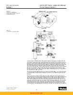
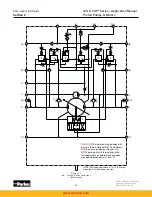
In both circuits the area shown in red is the high pressure work port and the area shown in
green is the low pressure work port. In the high pressure port, high pressure is exposed to
the blocked side of the replenishing check valves, the blocked side of the small check valves
going to the top of the dual level relief valves in the compensator circuit, and to the underside
of the sequence valves in the pressure compensator circuit. When the pressure in the work
port exceeds the setting of the pressure compensator override pilot section, the pilot section
will open, allowing flow into the replenishing gallery. This small flow creates a pressure drop
across the orifice in the bottom of the high pressure sequence valve, and the valve opens.
This allows oil to flow into the override tube which carries it to the appropriate vane chamber.
This pressure overrides the manual rotary servo control pressure and changes the pump
displacement.
The sequence valve has equal areas above and below the poppet. Secondary port pressures
are not exposed to any unbalanced areas of the poppet and therefore the sequence valve
setting is independent of downstream pressure.
The pressure in the override tube is limited by the dual level relief valve which has servo
pressure on its top area. The annular area is half of the area on top of the dual relief valve,
therefore the pressure in the override tube is limited to twice servo pressure plus the spring
force. Excess flow which is not used to change the stroke of the pump is ported directly into
the replenishing gallery through this valve.
PRESSURE COMPENSATOR
OVERRIDE
www.comoso.com


