


HY28-2668-01/GC/NA,EU
GOLD CUP
®
Series - Application Manual
Piston Pumps & Motors
3.13
Parker Hannifin Corporation
Hydraulic Pump Division
Marysville, Ohio USA
SERVO
PRESSURE
PRESSURE
COMPENSATOR
FLOW CONTROL
SHOE
CONTROLLED
ORIFICES
PISTON
PIN
TO
OVERRIDE
PRESS.
TO
OVERRIDE
PRESSURE
COMPENSATOR
FLOW CONTROL
PRESS.
PIN
PISTON
Section 3
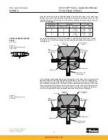
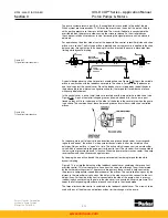
The pump system pressure port (A or B as applicable) is connected to the end of the pin.
When system pressure exceeds 12.25 times the pressure on the end of the piston, the pin
shifts, porting pressure to the cross drilled hole. The cross drilled hole is connected to the
override tube on the pressure side, causing the stroke to reduce. As the stroke reduces,
the shoe controlled orifice reduces in size, increasing the signal pressure until a balance is
obtained.
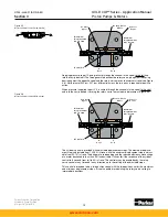
For operation on the other side of center, the opposite flow control, intensifier piston and shoe
orifice are in control. The first shoe orifice is blocked and servo pressure is applied to the shoe
balance area through that path. By keeping this orifice blocked, the pump is prevented from
limiting while dynamic braking.
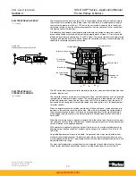
A special designed servo shoe (torque limit override shoe see Figure 3.18) forms the variable
orifice in conjunction with the feedback cover plate. The shoe is carried in the feedback arm
and travels against the control cover. Since the feedback arm is trapped by the bolt heads in
the balance plate (see internal configuration chapter) the torque limit override shoe follows
with pump displacement.
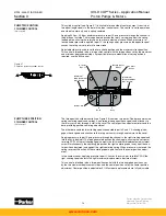
In the control cover, a pair of small holes are located over the torque limit override shoe (see
Figure 3.18). A pair of comet-tail shaped grooves (shown darkened) in the shoe are posi-
tioned so they will travel under one or the other of the holes in the cover plate when the pump
is on stroke. The combination of these holes and grooves forms the variable shoe controlled
orifices.
As the pump moves off of neutral in one direction, one groove travels under its correspond-
ing hole and “opens” the orifice. As the pump increases stroke further, the variable orifice
enlarges. Only one orifice is “open” at a time. The orifice which is open controls an intensifier
valve which is connected to the gage port for the outlet port. The closed orifice is connected to
the low system pressure side and is inactive. When the pump rocker crosses center, the pump
reverses flow and the orifices exchange functions.
By keeping the one orifice closed, the pump is prevented from being torque limited while
dynamic braking.
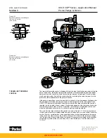
Figure 3.19 is a simplified drawing of the feedback control cover containing the torque limit
override control. Oil at servo pressure flows from the servo stem through the orifices formed
by the limiter adjusting screws. The pressure drop across these screws is held constant by
the pressure compensator spools downstream of the orifices. The controlled flows pass by the
pistons in the intensifier valves and out the holes in the side covers which connect to the vari-
able orifices. For the side of the control connected to the side of the pump which is pressur-
ized during dynamic braking, the hole in the side cover is connected with servo pressure.This
keeps the corresponding intensifier piston and control pin in the closed mode.
The torque limit override control is contained in the feedback control cover. This allows it to be
used with any of the other control options without further changes to the pump.
Figure 3.18
Torque limit override shoe
Figure 3.17
Torque limit override circuit
www.comoso.com


