background image


22 


7


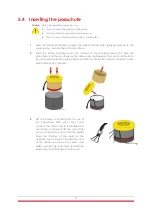
Hold the lines adjacent to the parachute, and fold them in a figure 8 shape using two 
fingers, all the way to the main strap (the main strap should fold once into the figure 8 
shape) and lock them together with a thin rubber band. 
Do not fold the rubber band, it is supposed to be rather lose. 

Placing the parachute inside the canister necessitates the folded parachute, the yellow cap, 
the red base and a new pyro actuator: 

8


Remove the used pyro-actuator from the socket in the bottom of canister. 

9


Place a new Pyro-actuator in place according to the above mentioned 

procedure

. 

10


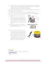
Place the red base into the bottom of the 
canister. 

11


Place  all  the  lines  at  the  bottom  of  the 
canister on the red base, so that the folded 
part  of the main strap (figure 8 shape) is put 
first on the red base and the rest of the lines 
are  placed  above  it.  The  rest  of  the  main 
strap  should  come  out  of  the  canister 
opening. 

12


Insert  the  parachute  to  the  canister  in 
zigzag folds. Keep constant pressure on the 
folds for the parachute to fit. 


13


Do not remove your hand  from the top of 
the  parachute.  With  your  other  hand, 
connect  the  main  strap to the  bridles and 
secure  the  carabiner.  Fold  the  main  strap 
on top of the parachute so that the bridles 
leave  the  canister,  at  one  point  on  the 
opposite side to the SAP, towards the front 
of  the  drone  and  place  the  yellow  cap. 
Make sure the cap is secured and that the 
parachute is not sticking out of the cap. 


Fly Safely!  

Should you have questions, contact our support team at –


[email protected]


Phone – +972-36885252


Summary of Contents for SafeAir M-600 Pro

Page 1: ...SafeAir M 600 Pro INSTALLATION GUIDE ...

Page 2: ...em to the Drone 11 5 3 Inserting the Pyro actuator 12 5 4 Inserting the parachute 13 5 5 Connecting the parachute cable and the TerminateAir cable to the SmartAir 14 5 6 Flight Preparations 14 REMOTE CONTROLLER OPTIONAL 15 6 1 RC System Port switches 15 6 2 RC System Status and Troubleshooting 16 6 3 RC System Specifications 16 SYSTEM LED INDICATIONS 17 OPERATING GUIDELINES 19 8 1 Preflight 19 8 2...

Page 3: ...ety Systems and protected by applicable copyright laws and international treaty provisions ParaZero Drone Safety Systems retains all rights not expressly granted No part of this publication may be reproduced in any form whatsoever or used to make any derivative work without prior written approval by ParaZero Drone Safety Systems All other trademarks are the property of their respective owners Othe...

Page 4: ... autonomous identification and activation capability using its dedicated SmartAir Pro Autonomous Trigger System 3 A DJI M600 dedicated independent flight termination system called TerminateAir The M600 TerminateAir controls the power supply to the motor drivers for emergency shutdown The system is designed for fast assembly and detachment using only four tool free screws The SafeAir M 600 Pro dron...

Page 5: ...not found describes the technical specifications of the ystem Technical Specifications Criterion Specification Expected Reaction Time Up to 50ms Altitude loss until full deployment hover 7 10m Vertical speed of descent hover maximum takeoff weight between 10 5 15 5Kg 3 6 4 8m s Temperature Range 25 C to 55 C Maximum Wind Speed Flight Speed 55knots Humidity 95 ISA at zero wind and stabilized vertic...

Page 6: ...ttps parazero com product registration SafeAir M 600 System The system incorporates a safety pin which acts as an on off button and electrically prevents the activation of the system Do not remove the safety pin until specifically instructed to do so in this guide Congratulations on your purchase of the SafeAir Mavic Safety System This manual explains how the SafeAir M 600 Pro works and how to pro...

Page 7: ... yellow cap 3 A pyro actuator within a metal compartment 4 The TerminateAir M 600 with one cable connected to it 5 Four mounting legs 6 Twelve one M4 Screws for connection to the M 600 mounting plate they replace the existing screws a syringe with Loctite adhesive 7 Twelve one M3 nylock nuts to connect the TerminateAir electric connection to the bottom electric board 8 Six one M3 8 screws and wash...

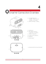
Page 8: ...afety pin Stage 1 Power on off Stage 2 Pyro safety B External damper holders A Safety pin B FTS UART connector optional Vin PWM C USB C connector D Parachute connector E RGB LED F Inner buzzer A Receiver latch for optional RC Front side Back side ...

Page 9: ...l it upwards along the Pull indications stickers 4 Insert the long screw in order to connect the TerminateAir to the left arm and close it firmly at the bottom using the provided toolset 5 Open the six screws connecting the power cables each connects two power cables for two engine controllers spread in a hexagon shape Then move the cables to the sides 6 Place the TerminateAir above the screw hole...

Page 10: ...ashers included in the package Make sure to apply Loctite 11 to each screw before inserting it Go through all the screws and nuts to verify they are firmly connected 11 Pull the cable attached to the TerminateAir along the M5 arm 12 Before closing the cover insert all 6 batteries and power up the drone If installation was performed correctly you should see 9 LEDs powering up If one of the LEDs doe...

Page 11: ...igure its position in the DJI assistant 1 Gently turn back the drone on its legs 2 Position the parachute system above the center plate in the correct orientation as seen in the picture below The two motors colored in red and the arrows on the GPS antenna show the front side of the M 600 3 Extract the original screws near the arms positioned near each of the SafeAir legs 4 Connect all 4 legs to th...

Page 12: ...its proper place Not to connect the parachute cable to the SmartAir 1 Unscrew the safety transportation capsule and take out the pyro actuator when taking out the pyro actuator from the transport capsule you are obliged to use protective glasses 2 Insert the pyro actuator into the socket in the bottom of the container make sure you push it all the way in ...

Page 13: ...irst Push the parachute in all the way Remove the yellow cap and Squeeze the parachute itself into the canister while removing the paper container out keep the paper container in a safe place for repack purposes 3 Do not remove your hand from the top of the parachute With your other hand connect the main strap to the bridles and secure the carabiner Fold the main strap on top of the parachute so t...

Page 14: ... operation for 2 hours Charge the SAP when the safety pin is all the way in 2 Optional Charge the RC using the provided USB cable for at least one hour before first use Charging should be made while the RC is turned off Caution When the RC is turned off or there is no link between the RC and the receiver manual triggering is not available 3 Using the desktop application allows for firmware update ...

Page 15: ...15 6 Remote Controller optional 6 1 RC System Port switches LED Lanyard hole Power switch Charging port Trigger switch Belt clip ...

Page 16: ...hes beeps No link SafeAir might be turned off or the RC is too far from the receiver 5 Yellow beep every 20 seconds RC battery low The RC will have enough power for 15 minutes It is advisable to end mission and charge the RC 6 Magenta flashes Trigger switch problem Try to manually release the Trigger switch and then turn the RC off and on again 6 3 RC System Specifications Range 1 km or line sight...

Page 17: ...or in active state 1 Check RC is on 2 Check that RC button is not pressed 3 Check RC is paired to device Flickering Yellow x2 NA System is not level Check system is positioned on a leveled surface Flickering Yellow x3 NA System storage error Format storage with ParaZero Desktop App Flickering Red x3 Repeating 3 beep pattern IMU error 1 Restart system 2 Contact Parazero support After init Solid blu...

Page 18: ...cy System was triggered and parachute deployed None Flickering Red x3 Repeating 3 beep pattern System battery is low Finish mission and charge system If system is armed it will continue to operate but if power will drop it will stop to function ParaZero Remote Controller RC is an optional add on and provides manual triggering ability The LED indication is applicable for RC equipped systems ...

Page 19: ...climbing you must climb to approximately 7 meters before the system is armed Climb until you hear a single long beep and the LED is GREEN The system is now armed and ready for activation in case of an emergency 8 3 Before Landing When approaching landing and the drone slowly while keeping it level Three seconds after the rotors are stopped on the ground the parachute system automatically disarms A...

Page 20: ...main parachute strap Inspect the canister SmartAir connectors and the TerminateAir to make sure that there is no apparent damage If there are tears or other suspected damage please contact us at support parazero com You will require all system components except the TerminateAir including a new pyro actuator for the repack process Before you start disconnect the FTS and parachute cables from the Sm...

Page 21: ...s under the folded parachute 6 Fold the left and right part of the folded parachute over each other Fold one side to the middle and then fold the other side on top of it It is important to keep the structure of the previous folds Start the folding process from one end and use weights to keep the parachute folded as you move along the length of the parachute ...

Page 22: ...om of the canister on the red base so that the folded part of the main strap figure 8 shape is put first on the red base and the rest of the lines are placed above it The rest of the main strap should come out of the canister opening 12 Insert the parachute to the canister in zigzag folds Keep constant pressure on the folds for the parachute to fit 13 Do not remove your hand from the top of the pa...

Page 23: ...23 Tel 972 36885252 30 Dov Hoz Kiryat Ono Israel 5555626 www parazero com Operate Drones Everywhere Safely ...

Reviews: