


E. Connectors, Cables, and Pin Assignments
E-12
September
2002
9128-A2-GB20-80
Standard V.35 Straight-through Cable
A standard V.35 straight-through cable can be used to connect a DTE port to a
DTE, where a 34-pin plug-type connector is needed for the data port and a
34-position socket-type connector is needed for the DTE. No special-order cables
are required.
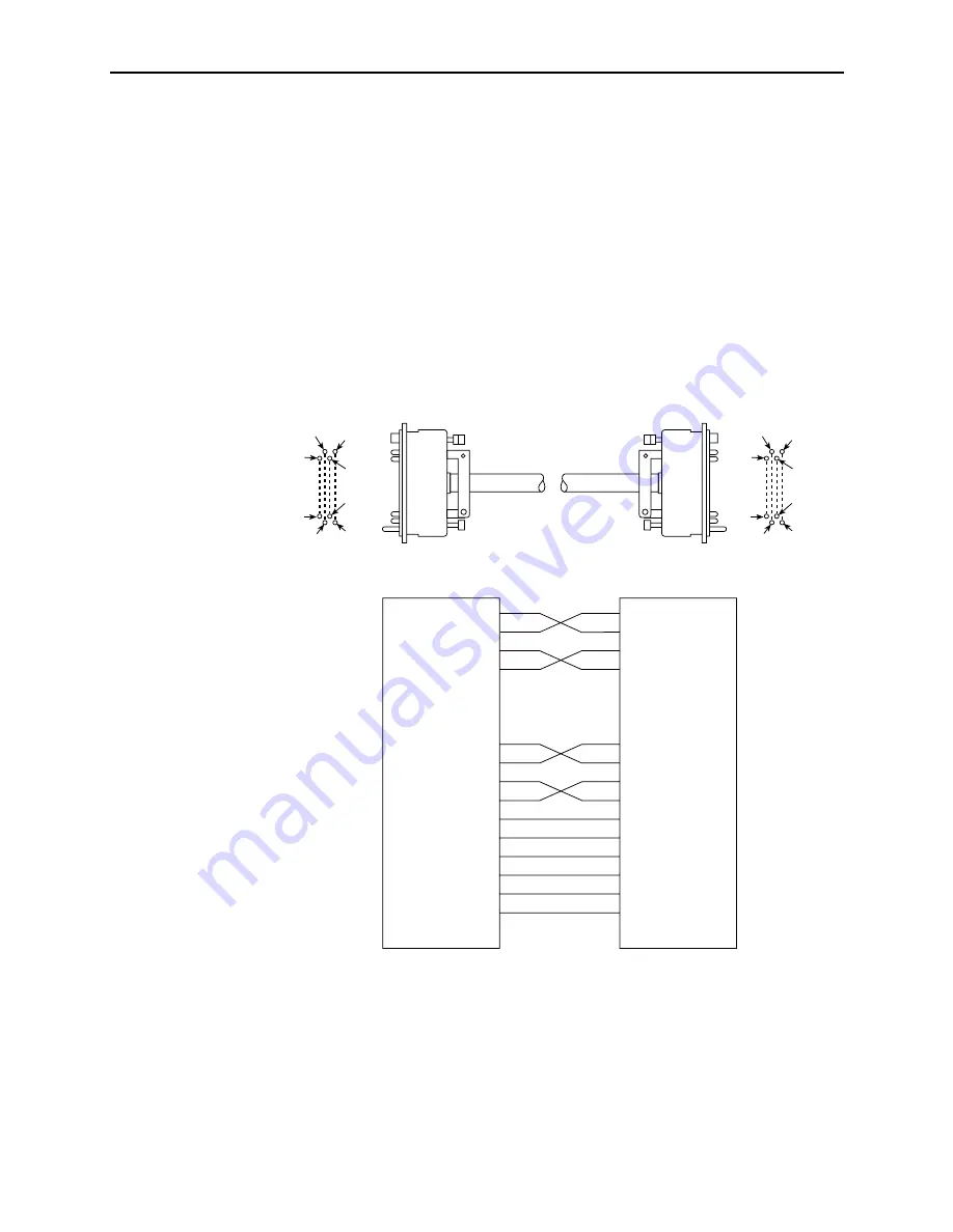
Standard V.35 Crossover Cable
A standard V.35 crossover cable with a 34-pin plug-type connector on each end of
the cable can be used to connect the FrameSaver unit’s DTE port to another DCE.
The following illustration provides the pin assignments for the V.35 crossover
cable.
TXD A
TXD B
RXD A
RXD B
TXC A
TXC B
RXC A
RXC B
ETXC A
ETXC B
FRM GND
SIG GND
RTS
CD
DTR
DSR
LL
P
S
R
T
Y
AA
Z
V
X
U
W
A
B
C
F
H
E
L
T
R
S
P
Z
AA
Y
W
U
X
V
A
B
F
C
E
H
L
P1
Pin
P2
Pin
98-16165a
C
A
B
D
LL
NN
MM
KK
C
A
B
D
LL
NN
MM
KK
Summary of Contents for 9126
Page 150: ...4 Configuration Options 4 106 September 2002 9128 A2 GB20 80 ...
Page 182: ...6 Security and Logins 6 16 September 2002 9128 A2 GB20 80 ...
Page 264: ...7 Operation and Maintenance 7 82 September 2002 9128 A2 GB20 80 ...
Page 348: ...A Menu Hierarchy A 4 September 2002 9128 A2 GB20 80 ...
Page 440: ...E Connectors Cables and Pin Assignments E 18 September 2002 9128 A2 GB20 80 ...


