


C. Router CLI Commands, Codes, and Designations
C-24
September
2002
9128-A2-GB20-80
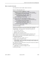
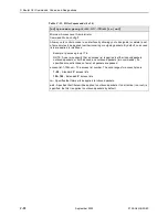
traceroute
[
protocol
]
dest
-
ip
[
source
source-ip
] [
length
bytes
]
[
timeout
time
] [
hops
hops
] [
interface
intf-type
intf-num
[.
sub-intf-num
]]
Minimum Access Level: Operator
Command Mode: Standard
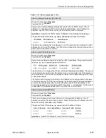
This command performs the TraceRoute test to the specified destination IP address. The
general format of the TraceRoute results is seen as follows:
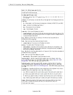
Tracing route to
x.x.x.x over a max of nn hops, with nnn byte packet:
1 <100ms <100ms <100ms
x.x.x.x
2 <100ms <100ms <100ms
x.x.x.x
3 <200ms <200ms <200ms
x.x.x.x
4 <200ms <200ms <200ms
x.x.x.x
The first column is the hop number, which is the Time to Live (TTL) value set in the IP
packet header. Each of the three next columns contains the round-trip time in 100ms
intervals for each attempt to reach the destination with that TTL value. If no response is
received, an * (asterisk) is displayed in place of the roundtrip time. The fifth column is the
IP address of the responding system. If no response is received for a hop, the last column
is blank.
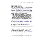
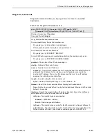
protocol – The protocol of the echo message for TraceRoute: ip.
dest-ip – Address of the device to TraceRoute.
source – The source IP address. The default source IP address is the IP address for the
interface on which packets are routed to the destination IP address.
source-ip – The source IP address used in the TraceRoute test. The default source IP
address will be the IP address for the interface on which packets are routed to the
destination IP address. The source IP address specified must be an IP address
assigned to an interface or sub-interface.
length – Specify the length of packets sent.
bytes – Number of data bytes. Range = 0–1500. Default = 64.
timeout – Specify the time in seconds before the TraceRoute test is abandoned.
time – Number of seconds before the TraceRoute test is abandoned. Range = 1–30.
Default = 5 seconds.
hops – Specify the maximum number of hops to be tested.
hops – The maximum number of hops to be tested. Range = 1–128. Default = 8.
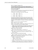
interface – Specify the target interface. The default target interface is the interface on
which packets are routed to the destination IP address.
intf-type – Two interface types are supported:
Ethernet – IEEE 802.3 interface
Serial – Frame relay serial interface
intf-num – The interface index number for the Ethernet and the Serial interfaces: 0.
sub-intf-num – The sub-interface number is only supported on the Network interface
(Serial 0). The following sub-interface numbers are supported: 0– 4,294,967,295.
Table C-12. Diagnostic Commands (2 of 2)
Summary of Contents for 9126
Page 150: ...4 Configuration Options 4 106 September 2002 9128 A2 GB20 80 ...
Page 182: ...6 Security and Logins 6 16 September 2002 9128 A2 GB20 80 ...
Page 264: ...7 Operation and Maintenance 7 82 September 2002 9128 A2 GB20 80 ...
Page 348: ...A Menu Hierarchy A 4 September 2002 9128 A2 GB20 80 ...
Page 440: ...E Connectors Cables and Pin Assignments E 18 September 2002 9128 A2 GB20 80 ...


