background image

UC300 Universal Converter

10

1. Clip the UC300 to the system panel box.
2. Plug in the PCS250/PCS250G cable between the UC300 serial port and the PCS250/PCS250G serial port. See 

Figure 3

 for the proper cable.

3. Connect the Tip and Ring from the UC300 to an outgoing telephone jack.
4. Connect the customer’s control panel Tip and Ring to the UC300 T1 and R1 terminals.
5. Connect the 12Vdc power supply to a supervised power supply.
6. Disconnect the cable from the UC300 Serial port and connect the IP150/UC300 to PCS250/PCS250G cable 

from the 307USB to connect to your laptop. This will allow you to configure the setup using BabyWare. See 

Figure 5


7. In BabyWare =>Accounts use Connection Option Serial.

Option #3: Both IP150 and PCS250/PCS250G Communication Devices 

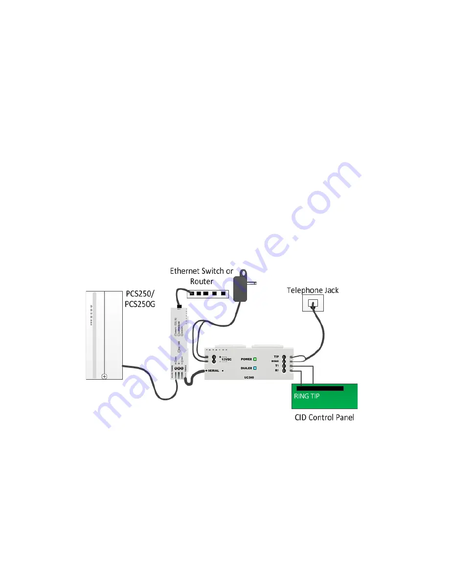
1. Clip the UC300 to the system panel box.
2. Clip the IP150 to the system panel box near the UC300.
3. Plug in the UC300 to the IP150 using the IP150 panel port and the UC300 serial port. See 

Figure 2

 for the 

proper cable.

4. Plug in the IP150 to the PCS250/PCS250G using the IP150 PCS250/PCS250G port and the PCS250/PCS250G 

serial port. See 

Figure 3

 for the proper cable.

5. Connect the Tip and Ring from the UC300 to an outgoing telephone jack.
6. Connect the customer’s control panel Tip and Ring to the UC300 T1 and R1 terminals.
7. Connect the 12Vdc power supply to a supervised power supply.
8. Connect an Ethernet cable from the IP150 to the LAN.
9. In BabyWare =>Accounts use Connection Option IP Static and connect through the IP150.

 Figure 6 – Connecting the UC300 with an IP150 and PCS250/PCS250G

Summary of Contents for UC300

Page 1: ...UC300 Universal Converter Reference and Installation Manual UC300 EI02 Printed in Canada 03 2015...

Page 2: ...all warranty terms and conditions Please ensure tat your use of the Paradox product is in compliance with local national and internal laws 2014 Paradox Security Systems Ltd All rights reserved Specif...

Page 3: ...figure Properties 17 4 3 Users 18 4 4 Reporting 19 4 5 GPRS Settings 21 4 6 SMS Settings 22 4 7 Configuring Receiver Settings 23 4 8 Trouble Reporting 24 4 9 Reporting Sequence Parallel or Serial 24 4...

Page 4: ...l Events are then forwarded to the monitoring station via IP150 and or PCS250 PCS250G The UC300 enables end users to self monitor their secured location by allowing receipt of instant SSL encrypted em...

Page 5: ...IPRS7 SDK using Paradox proprietary protocol with primary and secondary addresses for each receiver Emulates FXS telephone line which will allow panel reporting when there is no external telephone li...

Page 6: ...rial Reporting Backup defines the primary method for reporting and the number of failed attempts Once the number of failed attempts is reached the UC300 will switch to the backup reporting channels if...

Page 7: ...ng the Power Input to an AC DC power source must be performed only with a safety approved Limited Power Source LPS AC DC adaptor Note There is no need for a ground connection to the UC300 since the co...

Page 8: ...00 IP150 to PCS250 PCS250G 4 wire with one 0 8mm socket end and one 2 54mm socket end Figure 2 Connector Cable IP150 to UC300 Figure 3 Connector Cable IP150 UC300 to PCS250 PCS250G Description Special...

Page 9: ...supply to a supervised power supply or the auxiliary port of the control panel if it provides 12v supply 7 Connect an Ethernet cable from the IP150 to the LAN Warning Connecting the Power Input to an...

Page 10: ...nection Option Serial Option 3 Both IP150 and PCS250 PCS250G Communication Devices 1 Clip the UC300 to the system panel box 2 Clip the IP150 to the system panel box near the UC300 3 Plug in the UC300...

Page 11: ...reset switch for 5 seconds or until both status LEDs flash fast 2 Release switch 3 Press it again within the next 2 seconds to confirm the action After the reset an event will be stored in the event...

Page 12: ...00 Panel ID PC password Default 0000 and 0000 If you are connecting an IP150 you will need the IP module password Note If you are connecting PCS250 without the IP150 you will need to initiate the conn...

Page 13: ...00 Properties Reporting Network Settings Internet Settings set the IP address and port numbers to match the Accounts and router settings Go to your router web page and port forward the port according...

Page 14: ...UC300 Universal Converter 14 Figure 12 Bind the MAC to the IP Address 4 2 Configure Properties Figure 13 Home Screen...

Page 15: ...abyWare enter the User Identification and Number 000 and Code User 000 with code 123456 is the Master user The code can be changed for security purposes The end user needs this code to connect to the...

Page 16: ...0 set the network parameters in this dialog box The left tab is for IP150 and the right tab is for the PCS250G Note Settings vary according to the Internet provider Typically it will be DHCP Figure 16...

Page 17: ...Figure 18 Communications Settings Connection 3 Select Connection Tab 4 Click to locate the IP150 module on the LAN Figure 19 Select the IP150 Device 5 Click Configure If you make any changes to the d...

Page 18: ...gs If you are using a PCS250 PCS250G you must configure this page Figure 20 GPRS Settings Note These parameters are usually provided by the cellular network provider If you make any changes to the def...

Page 19: ...al Converter 4 6 SMS Settings You can set up to 8 phone numbers for SMS in BabyWare Figure 21 Configuring SMS Text Messages Phone Numbers If you make any changes to the default settings click OK to sa...

Page 20: ...the Internet The IP Addresses of the CMS and other monitoring stations is configured through BabyWare Receiver settings come from the CMS They supply you with all of the IP parameters of their server...

Page 21: ...Trouble Window If you make any changes to the default settings click OK to save your changes 4 9 Reporting Sequence Parallel or Serial To configure the reporting sequence parameters through BabyWare...

Page 22: ...make any changes to the default settings click OK to save your changes 4 11 1 Configuring Panel Monitoring Failure Report Panel Monitoring Failure Report feature enables continuous monitoring of the c...

Page 23: ...to disable this feature when using SP4 to avoid flooding the monitoring station with test report messages To disable this feature uncheck the Forward incoming Test Report message code 602 box 4 12 Fir...

Page 24: ...to a Reporting List As the Installer you need to 1 Do port forwarding on the IP150 in the router 2 Register the IP150 to ParadoxMyHome in BabyWare UC300 Reporting Network Settings Register For more i...

Page 25: ...for the UC300 Only Voltage input 12 15 VDC Weight 166g 5 86 OZ Dimensions H x W x D 4 0 cm x 10 3 cm x 2 3 cm 1 57in x 4 05 in x0 9 in Current consumption 60mA excluding the IP150 and the PCS250 PCS25...

Page 26: ...e Path SPT Supervised Premises Transceiver Redundancy and back up reports are not supported The product is intended to be installed inside a housing of another I HAS Intruder Hold Up Alarm Systems com...

Page 27: ...issing Landline missing Date and time lost IP150 module missing PCS250 PCS250G module missing Fail to com receiver 1 Fail to com receiver 2 IP150 Trouble Internet cable disconnected PMH polling error...

Page 28: ...complete satisfaction Should you have any questions or comments please do not hesitate to contact us For support please contact your local distributor or dial 1 450 491 7444 Monday to Friday from 8 0...

Reviews: