


BA_PH_245-100-300_EN_06-22.docx
32
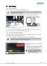
10.2
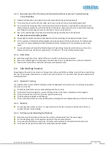
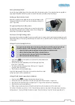
Emergency Stop Functions
In the event of danger or malfunctions in the work process,
the machine can be shut down quickly and reliably using the
following controls:
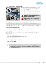
•
Via the emergency stop button on the control panel.
•
Via the emergency stop button on the table frame.
Before restarting the machine, the corresponding emer-
gency stop button must be unlocked again.
The braking time of the motor until standstill
can be up to 10 seconds.
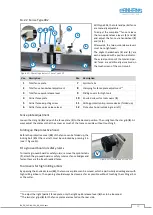
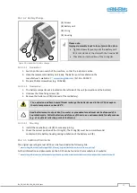
Figure 13: Emergency Stop Push Buttons
11
Tool Change
11.1
With Quick Clamping Device (Standard)
The tools used on the machine must comply with EN 847-1!
Wear cut-resistant protective gloves when changing tools!
•
Before changing the tool, switch off the spindle drive with the button .
•
Only Type 245|100
: Set brake release switch to “
Brake Release
” so that the spindle can be rotated manually.
•
Now turn the spindle by hand so that the clamping screw (
S
) is accessible.
•
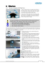
Press one of the two emergency stop buttons (
4
) and leave it locked.
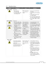
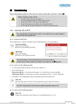
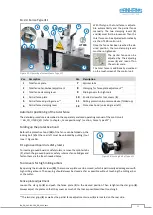
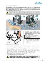
Figure 14: Milling arbor with quick clamping device
1.
Loosen the clamping screw (
S
) on the quick-re-
lease nut (
M
) with the supplied SW4 pin spanner.
2.
Then fully tighten the fixing
screw (
F
) by hand and remove
the quick-release nut (
M
) by
taking it out.
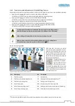
3.
Remove the spacer rings (
D
)
and put on the new cutter head.
Ensure that the clamping surfaces of the
spacer rings and clamping nut are clean.
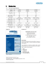
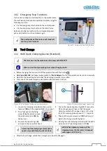
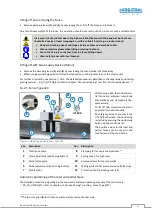
Figure 15: Marking for upper spacer ring
4.
Put on the required spacer rings (
D
), if necessary.
Place enough spacer rings so that the upper
clamping surface of the upper ring is in the area
(
E
) of the marking groove shown in
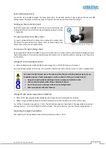
5.
Then put the quick-release nut (
M
) back on and
tighten the fixing screw (
F
) by hand.
6.
Now tighten the clamping screw (
S
) with the SW4
pin spanner
Tightening torque =
12 Nm
.
With 12 Nm tightening torque of the
clamping screw (S), the cutter is clamped
with approx. 30 KN (= 3 t).
•
After the tool change, unlock the emergency stop button (
4
) again
.
S
F
M
D
E