background image

4

Installation Guide

AT-HDR-EX-70-2PS

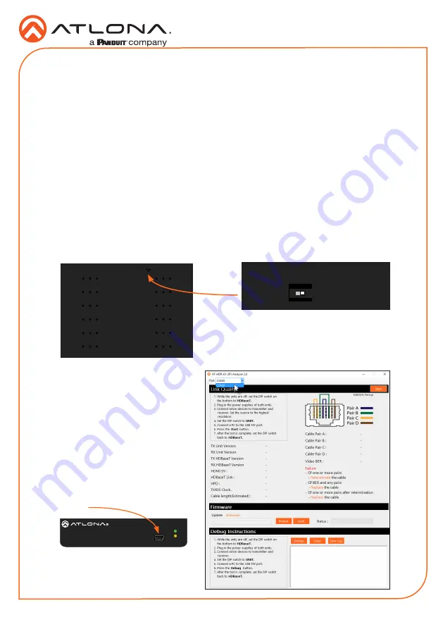
Testing HDBaseT Signal Integrity

The AT-HDR-EX-70-2PS Analyzer is a free, downloadable software application that is used to 

test the signal integrity of HDBaseT cables.  The software is available from Atlona.com, on the 

AT-HDR-EX-70-2PS product page.

1.  Download and run the 

AT-HDR-EX-2PS Analyzer.exe

 file.  The software comes with a 

ConnectorTool.dll

 file.  The DLL file must exist in the same folder as the executable, in order 

for the software to run.

2.  Verify that the DIP switch, on the bottom of the unit, is set to the 

HDBaseT

 position, as 

shown below.

3.  Reconnect power to both the 

transmitter and receiver.  Make 

sure that a signal is passing 

between the transmitter and the 

receiver.

4.  Set the DIP switch to the 

UNIT


position.

5.  Connect a USB-A to USB mini-B 

cable from the computer to the 

FW


port on either the transmitter or the 

receiver.

Requirements

• 

AT-HDR-EX-70-2PS-TX / AT-HDR-EX-70-2PS-RX

• 

AT-HDR-EX-70-2PS Analyzer software

• 

Computer running Microsoft Windows®

• 

USB-A to mini-B cable

FW

AT-HDR-EX-70-2PS-TX

POWER

LINK

DC 5V

HDBaseT OUT

HDMI IN

ON

1

FW

UNIT

HDBaseT

FW

AT-HDR-EX-70-2PS-TX

POWER

LINK

DC 5V

HDBaseT OUT

HDMI IN

ON

1

FW

UNIT

HDBaseT

FW

AT-HDR-EX-70-2PS-TX

POWER

LINK

DC 5V

HDBaseT OUT

HDMI IN

ON

1

FW

UNIT

HDBaseT

FW port

Summary of Contents for ATLONA HDR-EX-70-2PS

Page 1: ...n with locally powered transmitter and receiver endpoints as well as surface mounting hardware for discreet installation The HDR EX 70 2PS is ideal for residential applications with the latest as well...

Page 2: ...Refer to LED Indicators on page 4 for more information 3 LINK This LED indicator indicates the link status between the transmitter and the receiver Refer to LED Indicators on page 4 for more informati...

Page 3: ...HDR EX 70 2PS The information in the table below applies to both the transmitter and receiver unit POWER Description Solid green Unit is powered Off Unit is not powered Verify that the locking connec...

Page 4: ...hat the DIP switch on the bottom of the unit is set to the HDBaseT position as shown below 3 Reconnect power to both the transmitter and receiver Make sure that a signal is passing between the transmi...

Page 5: ...button 8 After testing is complete set the DIP switch on the bottom of the unit to the HDBaseT position Refer to the tables below for recommended cabling when using Altona products with HDBaseT The g...

Page 6: ...for the software to run 2 Disconnect power from the unit 3 Set the DIP switch on the bottom of the unit to the UNIT position as shown below 4 Connect a USB A to USB mini B cable from the computer to t...

Page 7: ...ton on the dialog box 11 Click the Load button within the AT HDR EX 70 2PS Analyzer software to begin the firmware update procedure During the update process the current progress will be displayed in...

Page 8: ...ing bracket 2 Use the enclosure screws to secure the mounting bracket to the enclosure 3 Repeat the above steps to attach the second mounting bracket to the opposite side of the unit 4 Mount the unit...

Page 9: ...bstantially similar replacement products exist Repair replacement or refund of Atlona products is the purchaser s exclusive remedy and Atlona liability does not extend to any other damages incidental...

Page 10: ...pering with this product any repairs attempted by anyone unauthorized by Atlona to make such repairs or any other cause which does not relate directly to a defect in materials and or workmanship of th...

Page 11: ...icular purpose shall provide to its products under applicable law If any product to which this limited warranty applies is a Consumer Product under the Magnuson Moss Warranty Act 15 U S C A 2301 ET SE...

Page 12: ...lona Inc All other brand names and trademarks or registered trademarks are the property of their respective owners Pricing specifications and availability subject to change without notice Actual produ...

Reviews: