


2
Installation Guide
AT-HDR-EX-70-2PS
FW
AT-HDR-EX-70-2PS-TX
POWER
LINK
DC 5V
HDBaseT OUT
HDMI IN
ON
1
FW
UNIT
HDBaseT
FW
AT-HDR-EX-70-2PS-TX
POWER
LINK
DC 5V
HDBaseT OUT
HDMI IN
ON
1
FW
UNIT
HDBaseT
FW
AT-HDR-EX-70-2PS-TX
POWER
LINK
DC 5V
HDBaseT OUT
HDMI IN
ON
1
FW
UNIT
HDBaseT
FW
AT-HDR-EX-70-2PS-RX
POWER
LINK
DC 5V
HDBaseT IN
HDMI OUT
ON
1
FW
UNIT
HDBaseT
FW
AT-HDR-EX-70-2PS-RX
POWER
LINK
DC 5V
HDBaseT IN
HDMI OUT
ON
1
FW
UNIT
HDBaseT
FW
AT-HDR-EX-70-2PS-RX
POWER
LINK
DC 5V
HDBaseT IN
HDMI OUT
ON
1
FW
UNIT
HDBaseT
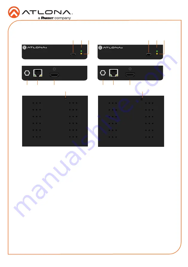
Panel Descriptions
1
FW
Connect a mini-USB to USB-A type
cable from this port to a computer, to
update the firmware. Refer to
Updating
the Firmware
, on page 5, for more
information.
2
POWER
This LED indicator glows solid green
when the unit is powered. Refer to
LED Indicators
, on page 4, for more
information.
3
LINK
This LED indicator indicates the link status
between the transmitter and the receiver.
Refer to
LED Indicators
, on page 4, for
more information.
4
DC 5V
Connect the included power supply to this
power receptacle.
5
HDBaseT OUT
Connect an Ethernet cable from this port
to the
HDBaseT IN
port on the receiver.
6
HDMI IN
Connect an HDMI cable from this port to a
UHD/HD source.
7
HDBaseT IN
Connect an Ethernet cable from this
port to the
HDBaseT OUT
port on the
transmitter.
8
HDMI OUT
Connect an HDMI cable from this port to
an UHD/HD display.
9
FW (UNIT / HDBaseT)
Set this switch to the
UNIT
position to
update the firmware. Refer to
Updating
the Firmware
, on page 7, for more
information. For normal operation or
for HDBaseT cable testing, set to the
HDBaseT
position. Refer to
Testing
HDBaseT Signal Integrity
, on page 5, for
more information.
Transmitter
Front
Front
Rear
Rear
Bottom
Bottom
Receiver
4
4
5
7
6
8
2
9
9
2
1
1
3
3


