background image

78

File name to be converted

(/almctrl.html if the paramete is omitted.)

Alarm

image control

(See page 80.)

Description

Alarm Operation

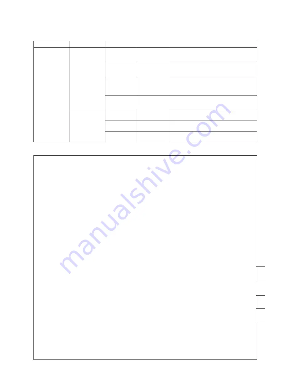
CGI functions related to alarm

Alarm images and log files recorded in the WJ-NT104 can be queried by using the following commands.

CGI item

URL

Parameter name

Parameter

Alarm log

file list

/cgi-bin/almlog

TARGETI

HTML

frame name

Alarm image display target name

(A new window is opened, if the paramete is
omitted.)

/cgi-bin/almctrl

TARGETC

HTML

frame name

Alarm image control frame target name

(The control frame cannot be used, if the para-
mete is omitted.)

BGCOLOR

000000

-FFFFFF

Background color

(Default color of the browser, if the paramete is
omitted.)
(Hexadecimal, 6-bit or HTML color name)

IMGHTML

file name

HTML file name for the alarm image frame

(Direct display of images, if the paramete is omit-
ted.)

LNO

000

-FFFF

Alarm image log number

(hexadecimal, 4-bit)

FNO

00-FF

Alarm image frame number

(hexadecimal, 2-bit)

FILE

file name

<HTML>
<BODY BGCOLOR=”#FFC1C2”>
<CENTER>
<B>ALARM IMAGE CONTROL PANEL
<SCRIPT LANGUAGE=”JavaScript”>

document.write(“(“+(0x%c+1)+”/”+(0x%t+1)+”)”)

</SCRIPT>
</B>
<TABLE BORDER=3 width=95% BORDERCOLOR=black bgCOLOR=”#DCFEFF”>

<TR>

<TH BORDER=3 BGCOLOR=black> <FONT SIZE=2 COLOR=”#DCFEFF”>

GO TO FIRST FRAME

</TH>
<TH BORDER=3 BGCOLOR=black><FONT SIZE=2 COLOR=”#DCFEFF”>

FRAME AT <BR>ALARM EVENT</TH>

<TH BORDER=3 BGCOLOR=black><FONT SIZE=2 COLOR=”#DCFEFF”>

GO TO LAST FRAME</TH>

<TH BORDER=3 BGCOLOR=black><FONT SIZE=2 COLOR=”#DCFEFF”>

PREVIOUS FRAME</TH>

<TH BORDER=3 BGCOLOR=black><FONT SIZE=2 COLOR=”#DCFEFF”>

NEXT FRAME</TH>

</TR>
<TR ALIGN=”center”>

<TD><A HREF=”/cgi-bin/almctrl?LNO=%l&FNO=%h&FILE=almimg.html” TARGET=”almimg”

onClick=”location=’/cgi-bin/almctrl?LNO=%l&FNO=%h’”>

<IMG SRC=”/button.jpg” BORDER=0></A></TD>

<TD><A HREF=”/cgi-bin/almctrl?LNO=%l&FNO=%a&FILE=almimg.html” TARGET=”almimg”

onClick=”location=’/cgi-bin/almctrl?LNO=%l&FNO=%a’”>

<IMG SRC=”/button.jpg” BORDER=0></A></TD>

<TD><A HREF=”/cgi-bin/almctrl?LNO=%l&FNO=%t&FILE=almimg.html” TARGET=”almimg”

onClick=”location=’/cgi-bin/almctrl?LNO=%l&FNO=%t’”>

<IMG SRC=”/button.jpg” BORDER=0></A></TD>

<TD><A HREF=”/cgi-bin/almctrl?LNO=%l&FNO=%p&FILE=almimg.html” TARGET=”almimg” onClick=”loca-

tion=’/cgi-bin/almctrl?LNO=%l&FNO=%p’”>

<IMG SRC=”/button.jpg” BORDER=0></A></TD>

<TD><A HREF=”/cgi-bin/almctrl?LNO=%l&FNO=%n&FILE=almimg.html” TARGET=”almimg”

onClick=”location=’/cgi-bin/almctrl?LNO=%l&FNO=%n’”>

<IMG SRC=”/button.jpg” BORDER=0></A></TD>

</TR>
</TABLE>
</CENTER>
</BODY>
</HTML>

HTML Sample File [almctrl.html]

z

x

c

v

b

Summary of Contents for WJ-NT104

Page 1: ...onnect or operate this product please read these instructions carefully and save this manual for future use Model No WJ NT104 Network Interface Unit Operating Instructions OPERATE RCV XMT LINK Network Interface Unit WJ NT104 ...

Page 2: ...EFER SERVICING TO QUALIFIED SERVICE PERSONNEL CAUTION RISK OF ELECTRIC SHOCK DO NOT OPEN SA 1965 SA 1966 NOTE This equipment has been tested and found to comply with the limits for a Class A digital device pursuant to Part 15 of the FCC Rules These limits are designed to provide reasonable protection against harmful interference when the equipment is operated in a commercial environment This equip...

Page 3: ...PROCEDURES 40 How to Read ADMINISTRATOR SETUP PAGE 40 MODE SETUP 41 NETWORK SETUP 43 ALARM SETUP 44 SERIAL PORT SETUP 46 MODEM SETUP 47 USER SETUP 48 HOST SETUP 49 FTP CLIENT SETUP 50 DATE TIME SETUP 52 CAMERA MENU SETUP 53 UTILITY SOFTWARE 54 Network Setup 54 Camera Menu Setup 56 ACCESS AUTHORIZATION 57 Control of Access Authorization 57 Access Level 57 Registration 58 EXTENSION FUNCTIONS 59 WJ F...

Page 4: ...n alarm unit Controls CCTV equipment options connected via RS 232C or RS 485 Combined with a modem provides PPP Point to Point connections Comes with a home page template which can be cus tomized by rewriting the HTML file using FTP File Transfer Protocol Designed for rack mounting using the optional WV Q204 1 mounting brackets Use of the optional WV Q204 2 mounting brackets per mits mounting up t...

Page 5: ...te action if the appliance becomes wet Turn the power off and refer servicing to qualified service personnel Moisture may damage the appli ance and also cause electric shock Do not use strong or abrasive detergents when cleaning the appliance body Use a dry cloth to clean the appliance when it is dirty When the dirt is hard to remove use a mild detergent and wipe gently Do not operate the applianc...

Page 6: ...32C MODE RESET q w e r t y u i q Operate indicator OPERATE Is on while the power of the WJ NT104 is turned on w Link indicator LINK Lights when the unit is connected to a normally operat ing network e Receiving indicator RCV Lights when data is received from the network r Transmitting indicator XMT Lights when data is transmitted to the network t Front panel y Reset button RESET Used to set or cha...

Page 7: ...termination ON Full Duplex 4 Lines termination ON Half Duplex 2 Lines termination OFF Full Duplex 4 Lines termination OFF It takes a few minutes after SW2 is set to ON and the RESET button is pressed for the data to be initialized After initializing set SW2 back to OFF and press the RESET button again to restart To return all data including settings and home page to the factory default settings se...

Page 8: ...and Rack mounting bracket small Rack mounting bracket small 1 Remove the four rubber feet by removing the four screws from the bottom of the WJ NT104 Mounting one WJ NT104 with the WV Q204 1 2 Fix the mounting brackets large and small on both sides of the WJ NT104 with the eight supplied screws M3x8 as shown below Mounting two WJ NT104 with the WV Q204 2 2 Place the joint metals on the WJ NT104 un...

Page 9: ...Mounting two WJ NT104s Cautions Do not block the ventilation opening or slots in the cover to prevent the appliance from overheating Always keep the temperature in the rack within 50 C 122 F Secure the rear of the appliance to the rack by using additional mounting brackets procured locally if the rack is subject to vibration ...

Page 10: ...AN Ethernet 10Base T Cable WJ NT104 Camera max 4 WJ NT104 LAN LAN PC browser Router Camera max 4 Access from PCs via routers Shown below is an example of monitoring from PCs on two or more subnets via routers for example IP address netmask and default gateway must be properly set FTP Client Function The FTP client supports the image uploading in normal and alarm modes Normal upload mode In this mo...

Page 11: ...ocol when an alarm input is received DB9 DB25 1 8 2 3 3 2 4 20 5 7 6 6 7 4 8 5 9 22 DB9 DB9 1 1 2 2 3 3 4 4 5 5 6 6 7 7 8 8 9 9 Connection via a dial up server or a router Set an WJ NT104 telephone number and IP address in the dial up server or ISDN POTS router in advance This configu ration enables the dial up server to access the WJ NT104 using PPP Point to Point Protocol when a PC specifies the...

Page 12: ... T LAN Type Connection The figure below shows how the WJ NT104 can be connected directly to a PC for testing before it is connected directly to a network The connection can also be made via a hub Direct Connection to a PC without Hub Connect the 10Base T port on the PC to the Ethernet port on the WJ NT104 with a crossover cable PC browser Ethernet crossover cable WJ NT104 Camera max 4 PC browser H...

Page 13: ...he PC s TCP IP to match the factory default settings of the WJ NT104 If your PC s OS is Windows95 or Windows98 proceed as follows 1 Click the Start button point to settings and then click Control Panel 2 Double click Network 3 In the Network dialog box click the Configuration tab 4 Choose TCP IP and then click the Properties button to display the TCP IP Properties dialog box 5 Specify an IP addres...

Page 14: ...tton to display the Manual Proxy Configuration dialog box 4 In the space Do not use proxy servers for domains beginning with specify 192 168 0 10 r In the Location bar specify http 192 168 0 10 t The browser displays the MAIN PAGE of the WJ NT104 s home page If there is a camera input it also displays the camera image y Click button on the home page and verify the func tions of the WJ NT104 For de...

Page 15: ...e TCP IP Properties dialog box before changing it to 192 168 0 9 WJ NT104 Setup First it is necessary to set an IP address for the WJ NT104 according to the operating environment Consult your network administrator for the address to set If the PC is running Windows95 or Windows98 select Control Panel Network Configuration click the Properties button to open the TCP IP Properties dialog box and ent...

Page 16: ...set previ ously hwsetup html to display the ADMINISTRATOR SETUP PAGE If it is not yet connected to a LAN connect to the LAN following the procedures described under PREPARATIONS p 12 and specify hwsetup html to open the ADMINISTRATOR SETUP PAGE q On the ADMINISTRATOR SETUP PAGE click the SERIAL PORT button to open the SERIAL PORT SETUP dialog box RS 232C SETUP TYPE Select MODEM TA BAUD RATE DATA B...

Page 17: ...d REDIAL NUMBER OF TIMES INTERVAL r Click the SET button to save t On the ADMINISTRATOR SETUP PAGE click the NETWORK button to open the NETWORK SETUP dialog box For NETWORK TYPE mark PPP y Click the SET REBOOT button to save The WJ NT104 is switched from LAN connection mode to PPP connection mode u Connect the RS 232C port on the rear panel of the WJ NT104 to the RS 232C port on the modem TA with ...

Page 18: ...tion speed etc of the client that will access the WJ NT104 e Connect a modem or TA to the PC and set it up The following description is based on the assumption that the device to which the modem or TA will be connected has already been set up For the modem or TA connection refer to the instruction manual for the modem or TA 2 Connection Setup To access the WJ NT104 set up the connection using Dial...

Page 19: ...hone number and click the Next button A message appears reading You have successfully created a new Dial Up Networking connection called t Click the Finish button The screen returns to the Dial Up Networking window The newly created icon is displayed y Right click the new icon to display the pull down menu and then click Properties ...

Page 20: ...ons field o Check TCP IP in the Allowed network protocols field 0 Click the TCP IP Settings button to display the TCP IP Settings dialog box 1 Check Server assigned IP address 2 Check Server assigned name server addresses 3 Remove checks from User IP header compression and Use default gateway on remote network 4 Click the OK button The screen returns to the Server Types dialog box Click the OK but...

Page 21: ...Connection Established dialog box is displayed after a short delay to indicate that the connection is under way With some versions of Windows95 this dialog box is not displayed e Double click the icon shown on the task bar to display the Connected to WJ NT104 dialog box which indicates that the connection is under way r To disconnect click the Disconnect button ...

Page 22: ...ng field y Check Allow any authentication including clear test in the Encryption settings field If the Dial Up Networking icon is not in My Computer it is not installed You can use the following procedure to install it 1 Right click the Network Neighborhood icon on the desktop and then click Properties in the pull down menu 2 In Network dialog box click the Services tab 3 If the Remote Access Serv...

Page 23: ...ing applies in cases where addresses from 192 168 1 10 to 192 168 1 15 can be pooled Click the OK button 1 Set Remote Access Admin to grant remote access permission to users To activate the Remote Access Admin 1 Click the Start button point to Programs and then Administrative Tools 2 Click Remote Access Admin 3 Point to Users menu and then click Permissions to display the Remote Access Permissions...

Page 24: ...tab at the top of the box and select a modem to use e Check Allow caller access r Click the Change Password button The Dial Up Networking Password dialog box is displayed t Enter a password and then click the OK button Type the same password as used to set up the connection and modem TA y Click the Server Types button to display the Server Types dialog box u For Types of Dial Up Servers select PPP...

Page 25: ...GE window is available in the following five modes 1 Images without camera control PULL mode 2 Images without camera control PUSH mode 3 Images with camera control PULL mode 4 Images with camera control PUSH mode 5 Others The mode 1 to 4 windows may differ slightly depending on the operation mode For the Main Page setup see MODE SETUP on page 41 MAIN PAGE AND CONTROLS ...

Page 26: ...ERATE Network Interface Unit WJ NT104 1 2 3 4 PC PC PC PC WJ NT104 CAMERA CAMERA CAMERA CAMERA Multi Input Selection Mode This mode switches periodically between multiple channels at high speed so that transmission to two or more users requesting different channels is possible There is no sudden change to another camera picture The image transfer rate is lowest in this mode Operation Modes The fol...

Page 27: ...ERA CAMERA CAMERA Channel Selection Fixed Input Selection Mode You cannot select other than the channels specified by ADMINISTRATION SETUP PAGE The image transfer rate is highest in this mode Sequence Mode This is an applied version of Random Input Selection Mode used to change channels at specified intervals Pan tilt zoom and other camera functions cannot be controlled in this mode ...

Page 28: ...est image is sent from personal computer PC browser Network WJ NT104 Newest image is continuously sent from the WJ NT104 Camera max 4 Coaxial cable video control Note To display images in pull mode requires Internet Explorer 4 0 Netscape Navigator 3 0 or a browser of a newer version which can execute Java Script Push Mode A request to send continuous images is sent from the PC to the WJ NT104 The ...

Page 29: ...W browser Incoming images with a resolution except of 640 x 240 pixels are displayed in the size in which they are received Incoming images with a resolution of 640 x 240 pixels are displayed in 640 x 480 pixel size Image Quality The following four image qualities compression ratios are available The lower the compression ratio the better the image quality but the large size of the image data file...

Page 30: ...e channels of the other users connected to the WJ NT104 to be switched to that same channel w Live image display Images of the selected camera are displayed on the default page as semi animated pictures Fixed Input Selection Mode q Live image display Only the images of the camera channels specified in the MODE SETUP window are displayed Note Ordinary users are barred from selecting video input cha...

Page 31: ...ameras in quad pattern on a single monitor screen see below e Live image display Images of the selected camera are displayed on the default page as semi animated pictures Quad Screen Mode index4 html q w q RETURN TO MAIN PAGE Restores Multi Input Selection mode w ALARM LIST Camera video input before and after alarm input can be temporarily stored in the internal memory of the WJ NT104 For alarm di...

Page 32: ...e image center Clicking the image center will not move the camera Zooming does not change the camera pan tilt angle Click the image repeatedly to move the camera to the desired position You cannot pan or tilt the camera continuously by dragging on the live image y ZOOM The connected combination camera option can be zoomed by clicking the TELE or WIDE button under ZOOM Clicking the TELE or WIDE but...

Page 33: ...rol cannot be retained by keeping the OPEN or CLOSE button depressed You need to click the OPEN or CLOSE button again o AUTOPAN The auto pan status of the connected combination camera option can be changed by clicking the ON or OFF button under AUTOPAN Note When LOCAL is selected in the camera setup AUTOPAN automatically stops after 1 minute When REMOTE is selected in the camera setup AUTOPAN will...

Page 34: ...he camera pan tilt angle Click the image repeatedly to move the camera to the desired position You cannot pan or tilt the camera continuously by dragging on the live image t ZOOM The connected combination camera option can be zoomed by clicking the TELE or WIDE button under ZOOM Clicking the TELE or WIDE button will operate the camera in telescopic or wide angle mode for a speci fied time after wh...

Page 35: ...will not move the camera Zooming does not change the camera pan tilt angle Click the image repeatedly to move the camera to the desired position You cannot pan or tilt the camera continuously by dragging on the live image u IRIS The connected combination camera option can be controlled to close or open the iris by clicking the OPEN or CLOSE button under IRIS Clicking the OPEN or CLOSE button will ...

Page 36: ...or NEAR button again o IRIS The connected combination camera option can be controlled to close or open the iris by clicking the OPEN or CLOSE button under IRIS Clicking the OPEN or CLOSE button will open or close the cam era iris for a specified time after which the operation is released automatically Clicking the RESET button on the screen will reset the iris of the displayed camera to the factor...

Page 37: ... the icon will display the alarm images e Alarm image display Alarm images are displayed in this space The image display size is specified in the MODE SETUP window Images for which size 640 x 240 was selected will be fitted to the screen 640 x 480 r ALARM IMAGE CONTROL PANEL For frame by frame display of alarm images in CON TINUOUS RECORDING mode The control panel is not displayed in SINGLE FRAME ...

Page 38: ...nd saved after the specified delay time The delay time from receiving an alarm until capture of the alarm image can be specified in the range of 0 to 10 sec onds in increments of 100 ms The number of images to save can be set to between 1 and 16 resolution 640 x 480 A frame rate of 1 10 1 5 3 10 1 2 1 2 3 5 or 10 can be selected If another alarm is received while recording an alarm the on going al...

Page 39: ...age 38 w Alarm log is overwritten Up to 100 alarm logs can be recorded e NT104 is restarted due to a change in settings r Power is switched back on or the reset button is pressed Number of frames recorded Number of alarm images to be recorded None in case Single Frame Recording mode Example If the PC on the alarm receiving end does not respond after a specified number of connection retries because...

Page 40: ... NT104 Remember however that any recorded alarm data will be deleted q MODE SETUP To set the default page when a file name is specified Also set operation mode image quality and camera control selection on this page w NETWORK To select LAN PPP and set the IP address network and default gateway e ALARM To set alarm input ON OFF alarm image save mode image overwrite YES NO number of images recorded ...

Page 41: ...ULTI INPUT SELECTION MODE If a channel set to OFF is selected the frame rate goes up because images are captured by skipping the channel set to OFF The factory default setting for channels are ON r INPUT CHANNEL SEQUENCE This item is available in RANDOM INPUT SELECTION MODE only Set sequence operation to ON or OFF The factory default setting is OFF t SEQUENCE INTERVAL This item is available in RAN...

Page 42: ... the highest frame speed The higher the number the lower the frame speed The factory default setting is 3 0 FRAME SPEED CONTROL FOR PUSH MODE Set a frame speed for PUSH mode This mode is supported by the Netscape Navigator browser only 1 is the highest frame speed The higher the number the lower the frame speed The factory default setting is 3 1 OUTPUT DATA RATE CONTROL Selecting a lower data rate...

Page 43: ... gateway to be used with PPP The factory default setting is 192 168 1 1 u REMOTE IP ADDRESS Used when PPP mode is on P to P ACCESS Enter the IP address of the PC which calls and access es the WJ NT104 The PC s IP address must be set to Obtain an IP automatically The factory default setting is 192 168 1 11 i PPP MODE P to P ACCESS mode To use this mode match the IP address of the PC with the addres...

Page 44: ...s to be recorded before and after an alarm is activated Note Depending on the recording mode this item is not shown on the window t FRAME RATE OF RECORDING FRAME Set a frame rate range for recording before and after an alarm is activated Note Depending on the recording mode this item is not shown on the window y ALARM CLEAR Clicking this button clears the alarm images and alarm log file saved in t...

Page 45: ...y from the WJ NT104 7 SENDER NAME Set the name of a mail sender up to 8 alphanumeric characters lower case 8 Destination E Mail address Specify the destination mail addresses of alarm notice recipients Up to 16 addresses can be set 9 Delete destination E Mail addresses Displays the list of e mail addresses to receive alarm notices Clicking the DELETE button will delete an address from the list 0 A...

Page 46: ...t for RS 232C The factory default setting is 1 bit t PARITY RS 232C Set the parity bit for RS 232C The factory default setting is NONE y USE FLOW CONTROL RS 232C Set flow control for RS 232C The factory default setting is NONE u TYPE RS 485 Set up the RS 485 port usage Select NONE or CAM ERA WJ SX550A The factory default setting is NONE i BAUD RATE RS 485 Set the baud rate for RS 485 to 1200 2400 ...

Page 47: ...PHONE NUMBER Set a telephone number for the WJ NT104 t DESTINATION TELEPHONE NUMBER Set the destination telephone numbers in case the alarm notice function is used y LOGON ID Set an ID code to log into the destination network when making calls from the WJ NT104 u LOGON PASSWORD Set a password to log into the destination network when making calls from the WJ NT104 i REDIAL NUMBER OF TIMES INTERVAL ...

Page 48: ...w USER REGISTRATION Set USER NAME PASSWORD and ACCESS LEVEL USER NAME and PASSWORD can be entered in up to 16 upper or lower case alphanumerics characters and symbols Select an ACCESS LEVEL 1 to 4 To change an already registered password and access level set them in the same way as to register a new password and access level and then press the SUB MIT button For user authorization refer to the ACC...

Page 49: ...Set a HOST IP ADDRESS and ACCESS LEVEL Select an ACCESS LEVEL 1 to 4 To change an already registered password and access level set them in the same way as to register a new password and access level and then press the SUBMIT button For host authorization refer to ACCESS AUTHORIZA TION on page 57 e DELETE HOST Select a registered HOST and press the DELETE button to delete The list of currently regi...

Page 50: ...ifies upload mode for FTP client SEQUENTIAL MODE The images are uploaded to the data port on default value PASSIVE MODE The images are uploaded to speci fied data port from FTP server q w e t y u r i o 0 1 2 Normal Setup t FTP ON OFF Selects to enable or disable image upload with the FTP periodically ON Enables upload OFF Disables upload The factory default is OFF y TARGET DIRECTORY Specifies the ...

Page 51: ... 0 FTP ON OFF Selects to enable or disable alarm image upload with the FTP when an alarm is received ON Enables alarm upload OFF Disables alarm upload The factory default is ON 1 TARGET DIRECTORY Specifies the absolute path for the directory of the FTP server when uploading the alarm images Note There are 3 alarm recording modes available Single Frame Continuous post images and Continuous pre and ...

Page 52: ...the device q DATE Set a date in the order of YY MM DD for example 99 01 23 for January 23 1999 The date is shown when this window is called on the screen w TIME Set a time in the order of HH MM SS for example 12 03 45 for 3 minutes 45 seconds past 12 o clock Use the 24 hour system for time setting The date is shown when this window is called on the screen q w ...

Page 53: ...ERA MENU e MOVE CURSOR Left To move the cursor to the left Use to change settings or adjust levels r MOVE CURSOR Up To move the cursor up t MOVE CURSOR Down To move the cursor down y MOVE CURSOR Right To move the cursor to the right Use to change settings or adjust levels u SET To execute the currently selected settings or to enter a submenu of the CAMERA MENU i ALL RESET To reset all camera setti...

Page 54: ... COA8000A for IP address 192 168 0 10 should appear in the WJ NT104 RESPONSE field If a wrong number is shown click the SET button again t To set the netmask Enter a set value into the NET MASK fields of the dialog box then click the SET button If the netmask has been set properly the response command REM and the set value entered in hexadecimal 8 bit notation e g REM FFFFFF00 for the set value 25...

Page 55: ...from 192 168 0 10 bytes 32 time 1ms TTL 255 Reply from 192 168 0 10 bytes 32 time 1ms TTL 255 Pinging 192 168 0 10 With 32 bytes of data Request timed out Request timed out Request timed out Request timed out Pinging 192 168 0 10 With 32 bytes of data Destination host unreachable Destination host unreachable Destination host unreachable Destination host unreachable C Windows ping 192 168 0 10 if t...

Page 56: ... Camera Setup r Select a channel under Camera Select t Click the MENU ON OFF button to open the Menu Should it not appear click the button repeatedly y Use UP DOWN LEFT RIGHT ENTER and ESC buttons to select a menu and execute a selected menu item For menu operations and setup refer to the operation manual of the connected camera u The SPECIAL button is effective only when the cursor points to SPEC...

Page 57: ...assword The access level is determined when both the user name and password are entered Access Level Four access levels can be assigned to control access by users More than one user can be assigned the same access level While device control commands are given top priority in the execution chain there is no priority attached to the access level It is possible to designate more than one network admi...

Page 58: ...w is provided with fields for making the necessary entries The factory default setting is USER NAME admin PASSWORD nil none ACCESS LEVEL 1 An admin user can change passwords but is not authorized to delete users or change access levels User Setup Window A maximum of 16 users can be registered in the USER SETUP window Enter a user name and password consisting of up to 16 alphanumeric characters cas...

Page 59: ...10 14 1 5 9 13 PUSH OPEN 16 POWER LOCK ON OFF ALARM MULTI SCREEN MULTISCREEN SELECT RESET SPOT SEQUENCE VCR CAM CAMERA PRESET POSITION Setup 1 On the ADMINISTRATOR SETUP PAGE click the SERIAL PORT button to open the SERIAL PORT SETUP window For TYPE select WJ FS616 Set the same communication parameters as for the WJ FS616 2 On the ADMINISTRATOR SETUP PAGE click the MODE SETUP button to open the MO...

Page 60: ...e connected combination camera option can be zoomed by clicking the TELE or WIDE button under ZOOM Clicking the TELE or WIDE button will operate the camera in telescopic or wide angle mode for a speci fied time after which the mode is released automatical ly These modes cannot be retained by keeping the TELE or WIDE button depressed You need to click the TELE or WIDE button again 0 FOCUS The conne...

Page 61: ...CV XMT OPERATE Network Interface Unit WJ NT104 1 1 1 1 PC PC PC PC WJ NT104 WJ SX550A B C MON1 MON2 MON1 MON2 MON1 MON2 MON1 MON2 Monitor Out 1 Monitor Out 2 Monitor Out 3 Monitor Out 4 Multi Input Selection Mode For VIDEO INPUT SELECTION MODE under OPERATION MODE SELECT mark MULTI INPUT SELECTION MODE This mode switches periodically between multiple channels at high speed so that transmission to ...

Page 62: ...nter the same 5 digit password as set for the Matrix Switcher w VIDEO INPUT NUMBER AND MONITOR OUT CHAN NEL SETUP Set a channel number for the monitor output of the WJ WJ SX550A Matrix Switcher to be connected to the video input connector on the WJ NT104 network inter face unit The status when selecting VIDEO INPUT at WJ NT104 in the above table is the same as when a monitor compatible with the WJ...

Page 63: ...ic or wide angle mode for a speci fied time after which the mode is released automatical ly These modes cannot be retained by keeping the TELE or WIDE button depressed You need to click the TELE or WIDE button again 1 FOCUS The connected combination camera option can be focused by clicking the FAR NEAR or AUTO but ton under FOCUS Clicking the FAR or NEAR button will operate the camera in focusing ...

Page 64: ... Selection Mode 1 Connect CAMERA 1 and 2 to the VIDEO IN 1 and 2 connectors on the rear of the WJ NT104 2 Connect the VIDEO OUT 1 and 2 connectors on the rear of the WJ NT104 to the VIDEO IN A and B connectors of the WJ DR200 3 Connect the VIDEO OUT connector of the WJ DR200 to the VIDEO IN 3 connector of the WJ NT104 4 Connect the RS 232C ports of WJ DR200 and WJ NT104 with a RS 232C cable For VI...

Page 65: ...larm recording on the WJ DR200 AV Disk Recorder w INDEX To search the disk for recorded frames Clicking the INDEX button opens the WJ DR200 RECORD LIST window Click the REFRESH button in the window to refresh the recording list displayed in the image win dow Then click the recording number to play back the selected frames To exit from search mode click the STOP button This button also toggles betw...

Page 66: ...play back frames in reverse order 1 STOP Clicking this button will terminate all modes of opera tion such as recording playback and setting 2 PLAY To play back frames in forward order 3 FF To play back a recording in forward search 4 REC To start recording in the previously defined mode 5 PAUSE Click to temporarily pause playback 6 TL MODE minus Clicking this button in playback will increase the p...

Page 67: ... Interface Unit WJ NT104 HD HD HD HD PC PC PC PC WJ NT104 VIDEO IN1 WJ HD100 MONITOR OUT OPERATE TIMER HDD ALARM SUSPEND DAYLIGHT SAVINGS FULL LOCK MEMORY CARD DISPLAY SELECT STOP PLAY REC PUSH PAUSE SET ALARM SEARCH STEP REW FF PLAY MODE SELECT SETUP ESC LCD CONTRAST Digital Disk Recorder WJ HD RS 232C DB9 DB9 2 3 3 2 4 6 5 5 6 4 7 8 8 7 Setup In the SERIAL PORT SETUP window set TYPE under RS 232...

Page 68: ...y To display the images previously selected as input 5 STOP Clicking this button will terminate all modes of opera tion such as recording and playback 6 PLAY To playback frames in forward order 7 REC To start recording in the previously defined mode 8 PREV FRAME Click in paused playback to move the playback opera tion back one step to the previous frame 9 NEXT FRAME Click in paused playback to adv...

Page 69: ...C PREVIEW INDEX STOP BPLAY PAUSE REC FWD REV ALARM SEARCH DISPLAY REC STOP 1 2 3 4 13 14 15 16 9 10 11 12 5 6 7 8 Digital Disk Recorder WJ HD FS 16 16 RS 232C DB9 DB9 2 3 3 2 4 6 5 5 6 4 7 8 8 7 Random input selection mode Enables control of cameras connected to the VIDEO IN connector of the WJ NT104 For VIDEO INPUT SELECTION MODE under OPERATION MODE SELECT mark RANDOM INPUT SELECTION MODE 1 Conn...

Page 70: ...nnect the RS 232C ports of the disk recorder and the WJ NT104 with a RS 232C cable LINK RCV XMT OPERATE Network Interface Unit WJ NT104 PC PC PC WJ HD500 WJ NT104 CAMERA 2 CAMERA 3 CAM2 CAM3 HD500 MULTISCREEN OUT REMOTE TIMER OPERATE FULL HDD SEQUENCE SET LOCK ALARM ALARM RESET ALARM SUSPEND MULTISCREEN SELECT SETUP ESC GROUP SELECT SPOT MULTISCREEN DAYLIGHT SAVINGS EL ZOOM COPY REC PREVIEW INDEX ...

Page 71: ... setup menu 6 SET Activates as the SET button of the disk recorder 7 RIGHT Moves the cursor to the right 8 Image Display To display the images previously selected as input 9 STOP Clicking this button will terminate all modes of opera tion such as recording and playback 0 PLAY To playback frames in forward order 1 REC To start recording in the previously defined mode 2 PREV FRAME Click in paused pl...

Page 72: ...u After finishing the transmission enter quit to exit from the FTP ftp quit Notes To transmit more than one file at a time enter prompt to release the interactive mode and follow mput of the input command with a wild card symbol for exam ple ftp prompt Interactive mode off ftp mput html Content Storage Memory Content files such as HTML that have been uploaded by means of the FTP are stored in the ...

Page 73: ...o carry out these functions When using a function the following syntax is used Syntax http IP address CGI function Parameter value Parameter value Image Display CGI function for image display HTML HEAD HEAD BODY BGCOLOR FFFFCC CENTER SCRIPT LANGUAGE JavaScript var myDate new Date var tmpImg new Image W H width W height H function drawcamera document CamImg src this src function loadcamera myDate n...

Page 74: ...Parameter name Parameter Parameter Camera control cgi bin camctrl CHSEL 1 4 Selecting a video channel Random Camera mode Enabled Multi Camera Fixed Camera mode Disabled CH 1 4 Selecting a camera to be controlled in the Multi Camera mode Random Camera and Fixed Camera modes are ineffective even if they are selected and com mands are applied only to the CH displayed PRESET 0 64 0 Calling a home posi...

Page 75: ... button jpg BOR DER 0 A TD document write TR document write FONT document write TABLE else if mode 1 document write FIXED INPUT SELECTION MODE else if mode 2 MULTI MODE ONLY document write MULTI INPUT SELECTION MODE CH SELECT FUNCTION document write P TABLE BORDER 2 BORDERCOLOR black width 90 BGCOLOR DCfeff document write TR document write TH BORDER 2 COLSPAN 4 BGCOLOR black FONT SIZE 3 COLOR DCfe...

Page 76: ...2 COLOR BLUE Copyright 169 1998 1999 Matsushita Communication Industrial Co Ltd BR All rights reserved FONT BODY HTML z If selecting a channel in the Random Input Selection mode set a value to argument CHSEL and carry out the CGI function camctrl x If selecting a channel in the Multi Input Selection mode the chconv function is used to make known the channel selec tion to the mainview html and camc...

Page 77: ... TD TD A HREF cgi bin camctrl CH c IRIS 0 IMG SRC button jpg BORDER 0 A TD TD A HREF cgi bin camctrl CH c ATPAN on IMG SRC button jpg BORDER 0 A TD TD A HREF cgi bin camctrl CH c ATPAN off IMG SRC button jpg BORDER 0 A TD TD FORM ACTION cgi bin camctrl INPUT TYPE hidden NAME CH VALUE c SELECT NAME PRESET SCRIPT LANGUAGE JavaScript for i 1 i 64 i document writeln OPTION i document writeln OPTION VA...

Page 78: ... 0x t 1 SCRIPT B TABLE BORDER 3 width 95 BORDERCOLOR black bgCOLOR DCFEFF TR TH BORDER 3 BGCOLOR black FONT SIZE 2 COLOR DCFEFF GO TO FIRST FRAME TH TH BORDER 3 BGCOLOR black FONT SIZE 2 COLOR DCFEFF FRAME AT BR ALARM EVENT TH TH BORDER 3 BGCOLOR black FONT SIZE 2 COLOR DCFEFF GO TO LAST FRAME TH TH BORDER 3 BGCOLOR black FONT SIZE 2 COLOR DCFEFF PREVIOUS FRAME TH TH BORDER 3 BGCOLOR black FONT SI...

Page 79: ...onally converted into internal parameters Any characters that begin with but are not substitute ones are displayed as they are for example k is displayed as k If a user wants to transmit a character string that is the same as a substitute one of the following methods can be chosen Example 37 m m Description Version Substitute character Action mode Camera channel m c Pull interval i In the Random I...

Page 80: ... of an alarm image for specified log number LNO 00 FF hexadeci mal 2 bit Specified frame c Same as the value of argument FNO 00 FF hexadecimal 2 bit Value of preceding argument FNO If FNO represents the first frame number h of the specified log number LNO the value of FNO is applied 00 FF hexadecimal 2 bit Preceding frame number p Value of preceding argument FNO If FNO represents the last frame nu...

Page 81: ... connected to the same subnet Are the IP addresses of the WJ NT104 and the client PC set for the same subnet Is the browser set to Use proxy server When accessing an NT104 on the same subnet it is recommended to select Do not use proxy server for the IP address WJ NT104 and client PC connected to different subnets Is the correct value set for the WJ NT104 default gateway No image is displayed Are ...

Page 82: ...to a hub for 10Base T or 10 100 BASE TX or a switching hub for 10Base T or 10 100 BASE Ethernet hub or Switching hub PERIPHERALS Network System CCTV Camera option Monitoring Browser Device Outline Modem To be used when connecting to a telephone circuit POTS Terminal adapter CCTV camera Available image modes Recommend Panasonic made Combination camera WV CS654 WV CS854 Outline Camera capable of ima...

Page 83: ...in D sub Connector RS 485 Terminal board Parallel Control Port Default 8 bit input I O selectable for all bits depending on the configuration Image Resolution Selectable from 640 H x 480 V 640 H x 240 V 320 H x 240 V or 160 H x 120 V Image Compression JPEG image quality selectable in 4 stages Installed protocol HTTP TCP IP PPP FTP SMTP Camera Coaxial Control Pan tilt Zoom Focus Preset Auto Focus f...

Page 84: ... San Gabriel Industrial Park Carolina Puerto Rico 00985 809 750 4300 Panasonic Security and Digital Imaging Company A Division of Matsushita Electric Corporation of America Executive Office One Panasonic Way 3E 7 Secaucus New Jersey 07094 Regional Offices Northeast One Panasonic Way Secaucus NJ 07094 201 348 7303 Southern 1225 Northbrook Parkway Suite 1 160 Suwanee GA 30024 770 338 6838 Midwest 17...

Reviews: