21
10.5. Charging And Discharging The Water
Charge The Water
1. Make sure all the piping installations are properly done.
2. Set the water supply valve
9
“OPEN” and water discharge valve
qa
“CLOSE”.
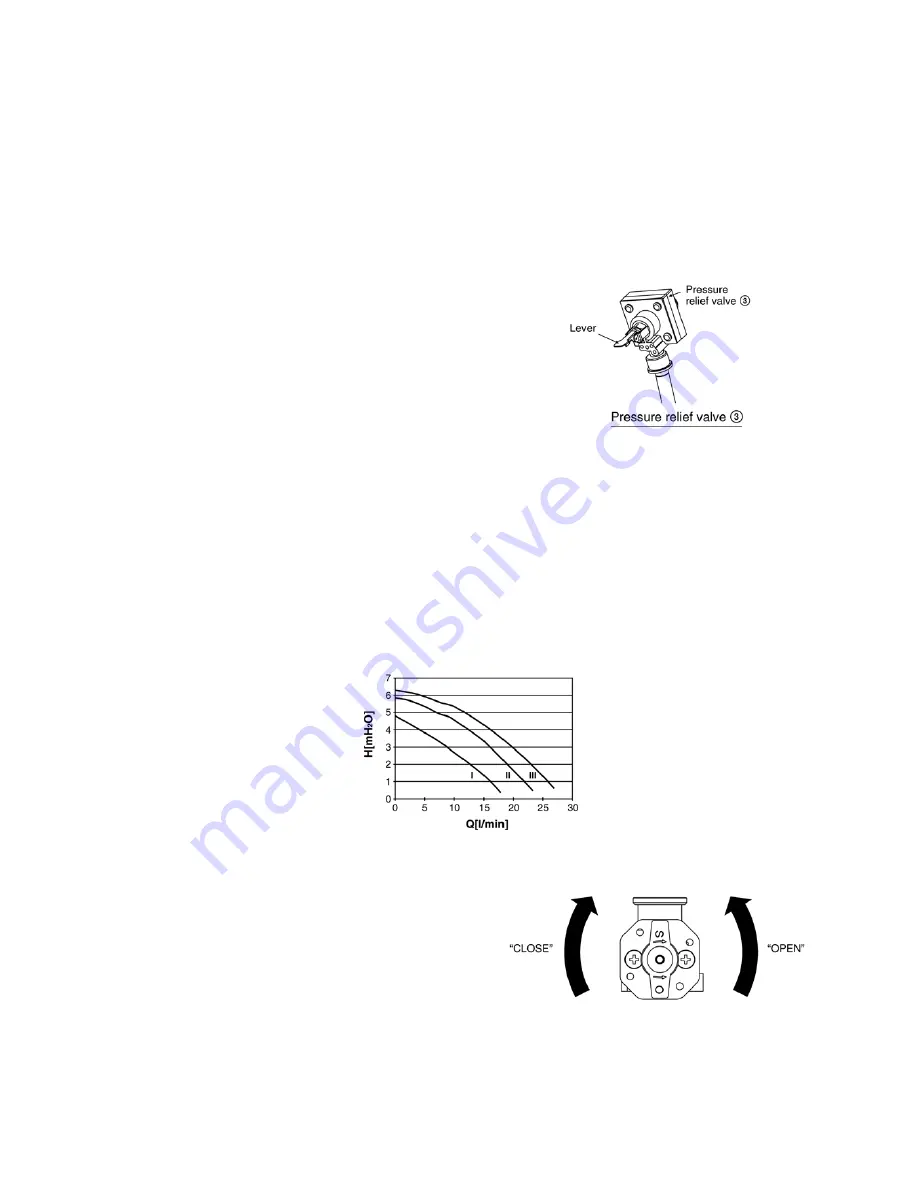
3. Pull up the lever of pressure relief valve
3
.
4. Start filling water to the Tank Unit. After 20~40min, water should flow out from drain hose outlet. Else, please contact your
local authorized dealer. Then push down the lever of pressure relief valve
3
.
5. Turn on the Tank Unit and make sure water pump
q;
and
qs
are running.
6. Check and make sure no water leaking at the tube connecting points.
7. After finish charging water, set the water supply valve
9
“CLOSE” and water discharge valve
qa
“CLOSE”.
Discharge The Water
1. Make sure all the piping installations are properly done.
2. Pull up the lever of pressure relief valve
3
located on top
of the Tank Unit.
3. Set the water supply valve
9
“OPEN” and water
discharge valve
qa
“OPEN”.
4. Water will start discharging from the Tank Unit.
5. After water complete discharged, set the water supply
valve
9
“CLOSE” and water discharge valve
qa
“CLOSE”. Push down the level of pressure relief valve
3located on top of the Tank Unit.
Release The Trapped Air In Water Circuit
• Make sure all the piping installations are properly done.
• Set the Water Supply Valve
9
“OPEN” and Water Discharge Valve
qa
“CLOSE”.
• Turn on the heating pump by force (continue press [Heating] for 5 seconds). Open/Close release valve to release air trap at the
top of the tank. (Refer to figure “Pressure relief valve
3
”). The trapped air will be drained out together with water.
• Repeat for a few times until the bubbling sound disappear.
• Stop the pump (press ON/OFF switch) and Close water supply valve.
How To Adjust The Water Flow Rate
The water flow rate can be adjusted by setting the water pump speed on the water pump
q;
and
qs
. The default setting is high
speed (III). Adjust it to moderate speed (II) and slow speed (I) if necessary (e.g. reduce the noise of running water).
The graph below show the external static pressure (H, in mH
2
O) versus water flow rate (Q, l/min).
How To Operate Water Supply Valve
9
And Water Discharge Valve
qa
• To “OPEN” the valve (make water start flow), turn the handle
counter-clockwise gently. If the flow does not occur after fully
open the valve, please contact your local authorized dealer.
• To “CLOSE” the valve (make water stop flow), turn the
handle clockwise gently.
Summary of Contents for WH-TX30B9E8
Page 7: ...7 4 Location of Controls and Components 4 1 Tank Unit 4 1 1 Location of Control ...
Page 8: ...8 4 1 2 Main Components ...
Page 9: ...9 5 Dimensions ...
Page 10: ...10 6 Water Cycle Diagram ...
Page 11: ...11 7 Wiring Connection Diagram ...
Page 12: ...12 8 Electronic Circuit Diagram 8 1 Indoor Unit ...
Page 13: ...13 9 Printed Circuit Board 9 1 Tank Unit 9 1 1 Main Printed Circuit Board ...
Page 14: ...14 9 1 2 Surge Printed Circuit Board ...
Page 47: ...47 15 2 Heater Removal Procedures ...
Page 48: ...48 15 3 Main Printed Board Removal Procedures ...
Page 49: ...49 15 4 Control Board Removal Procedure ...
Page 50: ...50 15 5 Pressure Relief Valve Procedures ...
Page 51: ...51 15 6 Flow Switch Removal Procedures 15 7 Water Pump Removal Procedures ...
Page 52: ...52 16 Technical Data 16 1 Pump Characteristic 16 2 Water Tank Sensor Characteristic ...
Page 53: ...53 ...
Page 54: ...54 ...


