


23
Ignition Electrical Parts Inspection and Maintenance
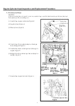
5. Cam angle sensor
(1) Cam angle sensor removal and installation
c
Remove the harness connector.
d
Remove the cam angle sensor.
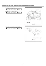
(2) Points to keep in mind during installation
c
Coat the O-ring with engine oil during installation.
d
Make sure that there are no foreign materials adhering
to the sensor
À
ange, O-ring, or front cover areas.
e
Do not bring close to magnetic
¿
elds.
f
Tighten the bolt after making sure that the sensor is
completely inserted into the front cover.
Bolt (width across
À
at)
10 [mm]
Tightening torque
6.4 - 7.5 [N·m]
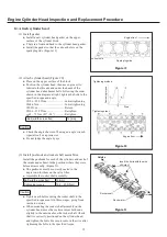
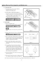
6. Spark plugs
(1) Remove the ignition coils.
Remove the bolts securing the ignition coils, and remove
the ignition coils (indicated by arrows in Figure 3)
Bolt (width across
À
at)
10 [mm]
Caution
Handle the ignition coils carefully. Keep them free from
shock.
(2) Using a spark plug wrench, remove all 4 spark plugs.
(Figure 4)
Bolt (width across
À
at)
16 [mm]
(3) If the tip of the plug is completely black with dry carbon,
the mixture may be too rich, the ignition timing may be
retarded, or oil may be going up and down within the
cylinder. Investigate these possibilities.
(4) If the tip of the plug is black and moist, the air
cleaner element may be clogged. Investigate this
possibility.
(5) If the insulator at the tip of the plug is burned
completely white, and a portion of it is melted
together with the electrode, the ignition timing may
be too advanced, there may be a problem with the
cooling system, the plug may not be suf
¿
ciently
tightened to the engine, or the mixture may be too
lean. Investigate these possibilities.
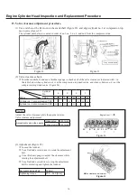
(6) Check for damage to the washer and cracking on the
insulator. (Figure 5)
(7) If the tip of the centre electrode is rounded as shown
in
c
, replace the plug with a new one. (Figure 6)
(8) If the ground electrode is worn as shown in
d
, replace the plug with a new one. (Figure 6)
Figure
.4
Figure
.5
Terminal
Insulator Electrode
Gap
Figure
.6
Centre electrode rounded
Ground electrode eaten away
Electrode loss
Figure
.3
Ignition coils
Ignition coil retaining bolts (4)
GHP̲Main̲Parts̲Replacement.indd 23
2012/07/31 17:54:24


