background image

81

English

Information timing

Set up the informing manner for no signal or 

temperature rising.

RS-232C controls:

Warning or error message sent from the display 

automatically.

LAN controls:

Acquire the warning or error message from the 

display.

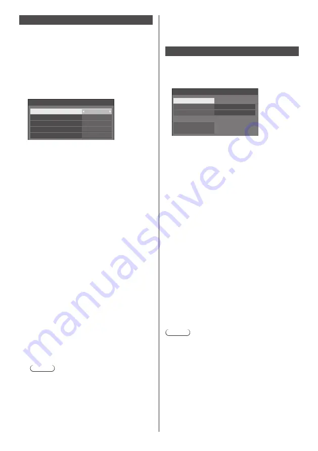
[Information timing] - submenu screen

Information timing

No signal warning

No signal warning timing

Temperature warning

No signal error
No signal error timing

On

5min

On

10min

On


[No signal warning]

When set to [On], the display sends out the no signal 

warning.


[No signal warning timing]

Set up the detecting time for no signal warning.
(Range: 01 ‒ 60, Interval: 1 minute)


[No signal error]

When set to [On], the display sends out the no signal 

error.


[No signal error timing]

Set up the detecting time for no signal error.
(Range: 01 ‒ 90, Interval: 1 minute)

● 

The warning of [No signal warning] and the error 

of [No signal error] are not sent when the no signal 

state is detected through any of the following 

functions: 
[No signal power off], [HDMI1 power management], 

[HDMI2 power management], [DisplayPort 

power management], [DIGITAL LINK power 

management], [DVI-D power management], [PC 

power management] (see page 64)

Setting Example:

● 

If there is no signal when [PC IN] is input, [PC 

power management] is activated first and the 

Display enters the standby mode.
[No signal warning timing]: 5 minutes
[No signal error timing]: 10 minutes
[PC power management]: [On] (60 seconds)

Note

● 

The [No signal error timing] cannot be set 

shorter than [No signal warning timing].

● 

Even when a USB memory is connected, if 

there is no playable file, the unit determines no 

signal is present.


[Temperature warning]

When set to [On], the display sends out the warning 

message.

SLOT settings

Set for SLOT.
This menu is displayed only when a function board is 

inserted into the SLOT.

[SLOT settings] - submenu screen

SLOT settings

SLOT power link

Off

SLOT power on

SLOT forced termination

SLOT information

SLOT standby

On


[SLOT information]

Displays the information of the function board inserted 

to the SLOT.


[SLOT power link]

Links the power operation of the SLOT with the power 

operation of this unit.

[Off]:

Does not link.

[On]:

The power of the unit is turned off when the power 

of the inserted function board is turned off during 

SLOT input or enters the power save mode. After 

that, when the power of the function board is 

turned on or returns from the power save mode, 

the power of the unit is turned on.


[SLOT standby]

Sets the power supply status for the SLOT when the 

unit is in standby mode.

[Off]:

The power is not supplied to the SLOT when the 

power is turned off by the remote control, etc.

[On]:

The power is supplied to the SLOT when the 

power is turned off by the remote control, etc.

Note

● 

When [SLOT standby] is set to [On], the power 

indicator in standby mode lights orange (red/green).


[SLOT power on]

Starts up the power of the SLOT.


[SLOT forced termination]

Forcibly turns off the power of the SLOT. Use this only 

when the power cannot be turned off manually due to 

the problem of the operating system, etc.

Summary of Contents for TH-98SQ1W

Page 1: ...Instructions Functional Manual UHD LCD Display For business use Model No TH 98SQ1W 98 inch model TH 86SQ1W 86 inch model English Please read these instructions before operating your set and retain the...

Page 2: ...tructions 4 FCC STATEMENT 5 Important Safety Notice 6 Safety Precautions 7 Precautions for use 10 Accessories 12 Accessories Supply 12 Remote Control Batteries 13 Attaching the USB Memory Cover 13 Att...

Page 3: ...eb Browser Control 92 Before Using Web Browser Control 92 Access from Web Browser 92 Operating with Web Browser 93 Using USB media player 102 Function description 102 Preparation 103 Playing back the...

Page 4: ...not block any ventilation openings Install in accordance with the manufacturer s instructions 8 Do not install near any heat sources such as radiators heat registers stoves or other apparatus includi...

Page 5: ...esired operation CANADIAN NOTICE This Class A digital apparatus complies with Canadian ICES 003 WARNING Not for use in a computer room as defined in the Standard for the Protection of Electronic Compu...

Page 6: ...e near sources of strong electromagnetic fields or where electrical noise may overlap with the input signals could cause the picture and sound to wobble or cause interference such as noise to appear T...

Page 7: ...l accessories may cause instability which could result in the possibility of injury Securely install the wall hanging bracket of the optional accessories Ask an authorized dealer for installation 4 or...

Page 8: ...power supply plug immediately use the wall outlet which you can reach easily Do not touch the unit directly by hand when it is damaged Electric shock could occur Do not stick any foreign objects into...

Page 9: ...e moving the Display If the Display is moved while some of the cables are still connected the cables may become damaged and fire or electric shock could result Disconnect the power supply plug from th...

Page 10: ...installed on the wall if the power cord and connection cables are difficult to remove and insert make connections first before installation Be careful not to allow the cables to be entangled After ins...

Page 11: ...ce of the liquid crystal panel or cabinet by using a soft cloth to remove dirt To remove stubborn dirt or fingerprints on the surface of the liquid crystal panel dampen a cloth with diluted neutral de...

Page 12: ...apter 1 DPVF2389ZA X1 Power supply cord Approx 2 m 1JP155AF1U 1JP155AF1W 2JP155AF1W 3JP155AF1W Attention Store small parts in an appropriate manner and keep them away from young children The part numb...

Page 13: ...eakup batteries Moreover batteries must not be exposed to excessive heat such as sunshine fire or the like Attaching the USB Memory Cover When using a USB memory device the USB memory cover can be att...

Page 14: ...ptor and bring the circuit board into contact with the hook one location and the end faces two locations securely Function board Hook End face End face 3 Using the screw removed in step 1 fix the func...

Page 15: ...ving The display has handles for carrying Hold them when moving Handle Note Do not hold parts other than the handles 4 or more people are required to carry this unit If this is not observed the unit m...

Page 16: ...he flat washer black left as it is Eyebolt Flat washer black 3 After removing the eyebolt tighten the eyebolt cap with the flat washer black left as it is Eyebolt cap Flat washer black Note Installati...

Page 17: ...r of the AC cord consult the dealer where you purchased the product When disconnecting the AC cord be absolutely sure to disconnect the AC cord plug at the socket outlet first The supplied AC cord is...

Page 18: ...p pushing both side snaps and pull out the clamper hole Insert the clamper in a hole To remove from the unit snaps 2 Bundle the cables Keep pushing the knob and pull out the tip hooks Set the tip in t...

Page 19: ...ee page 27 7 USB USB Terminal 2 systems Connect the USB memory to use USB media player or Memory viewer Also this can be used to supply power of up to 5V 1A front side terminal or 5V 2A far side termi...

Page 20: ...he sync signals output from PC or video equipment are disturbed for example when changing settings of video output the colour of the video may be disturbed temporarily The unit accepts YPBPR YCBCR sig...

Page 21: ...etect DVI D IN terminal connection Note Video equipment and cables shown are not supplied with this unit DVI D IN terminal is for Single Link only For audio the AUDIO IN 1 AUDIO IN 2 terminal can be u...

Page 22: ...and sizes have already been stored in this unit Computer signals which can be input are those with a horizontal scanning frequency of 30 to 110 kHz and vertical scanning frequency of 48 to 120 Hz The...

Page 23: ...Name R PR CR G Y B PB CB NC not connected GND Ground GND Ground GND Ground GND Ground 5 V DC GND Ground NC not connected SDA HD SYNC VD SCL DisplayPort IN DisplayPort OUT terminal connection DisplayPo...

Page 24: ...d ML_Lane 1 p ML_Lane 0 n GND Ground ML_Lane 0 p CONFIG1 CONFIG2 AUX_CH p GND Ground AUX_CH n Hot Plug Detect GND Ground 3 3 V DC output Daisy chain connection It is possible to daisy chain multiple d...

Page 25: ...PC Video Cassette Recorder DVD Player Note Video equipment and connection cables are not supplied with this unit When connecting with DIGITAL LINK be sure to configure each of the Network settings set...

Page 26: ...for SERIAL Terminal 6 7 8 9 1 3 4 5 2 Pin No Signal Name NC not connected RXD TXD Non use GND Ground Non use RTS Shorted in this set CTS NC not connected These signal names are those of computer speci...

Page 27: ...unit will send an ER401 command back to the computer When sending a command which does not require parameter a colon is not needed Consult your local Panasonic dealer for detail instructions on comman...

Page 28: ...display is on Stick PC commercially available USB cable commercially available HDMI extension cable commercially available When the picture is displayed depending on the USB terminal power of up to 5V...

Page 29: ...laylist edit function see page 109 data cloning function see page 121 etc Turn the unit off Do not frequently repeat connecting disconnecting the USB memory device Wait at least 5 seconds after connec...

Page 30: ...d green When the unit enters the standby mode using the following functions orange red green Standby state with the Power management function About Power management function see page 64 Standby state...

Page 31: ...enu screen see page 40 5 Unit Unit Adjusts the volume see page 36 On the main screen switches settings or adjusts settings level see page 40 6 Unit Unit Selects the setting item on menu screen see pag...

Page 32: ...size of the screen see page 42 11 INPUT Switches input to display on the screen see page 35 12 PICTURE see page 45 13 SOUND see page 44 14 RECALL Displays the current setting status of Input mode Aspe...

Page 33: ...unit to the direct sunlight or strong fluorescent light 1 Connect the AC cord plug to the Display see page 17 2 Connect the plug to the socket outlet Note Main plug types vary between countries The p...

Page 34: ...1 Select the language with and press ENTER English UK Deutsch Fran ais Italiano Espa ol ENGLISH US OSD language 2 For vertical installation select Portrait with and press ENTER Display orientation Lan...

Page 35: ...creensaver and the Wobbling function is recommended see page 62 63 RECALL It is possible to check the setting status of input label picture mode etc Press RECALL Current setting status will be display...

Page 36: ...r the volume level is changed While MUTE is active is displayed as a reminder after operation When the image set in No signal image settings see page 68 is displayed is not displayed after operation I...

Page 37: ...e displayed filling the screen Normal Pictures are displayed with the aspect ratio of input signals Native Pictures are displayed with the resolution of input signals H fit Pictures are enlarged to th...

Page 38: ...a public showing and then use the aspect mode select function to shrink or expand the picture you may be violating the copyright under copyright law It is prohibited to show or alter the copyrighted m...

Page 39: ...uttons displays the guide again 4 Exit the digital zoom mode Press RETURN to exit the mode The screen returns to the previous state just before entering the digital zoom mode and the digital zoom oper...

Page 40: ...rightness Colour Hue Sharpness Gamma Memory save Memory load Memory edit High Enhance level 6500K Colour temperature Dynamic contrast Colour enhancement Off Off Refine enhancer Colour management Grada...

Page 41: ...ic contrast Memory save Memory load Memory edit Off Off Enhance level High Setup menu see page 51 83 1 3 Setup Screensaver Signal Input label Power management settings Off timer function No activity p...

Page 42: ...condition This setting is enabled when an analogue signal PC is input and the aspect mode is set to Full see page 82 While displaying the picture of the corresponding signal select Auto setup and pre...

Page 43: ...ff Note This is enabled when the screen mode is set to Full Zoom1 or Zoom2 Note this setting is disabled when using USB MEMORY VIEWER input multi screen display of the multi display or digital zoom PC...

Page 44: ...dio output INTERNAL SPEAKERS Internal speakers output EXTERNAL SPEAKERS External speakers EXT SP terminal output AUDIO OUT AUDIO OUT terminal output When AUDIO OUT is selected the other menus are grey...

Page 45: ...e to the picture source or environment where this unit is used Vivid signage Suitable for signage applications featuring more vivid and sharper images in bright environments such as a shop Natural sig...

Page 46: ...temperature settings User1 and User2 can be stored 1 Press ENTER while setting Colour temperature 2 2 6500K Gamma Colour temperature Example When Colour temperature is 6500K it is possible to reflect...

Page 47: ...Adjusts brightness of colour 127 to 127 Reset Resets to defaults Select Yes with and press ENTER In ENGLISH US OSD language Hue is displayed as TINT Note When 6 segment is selected R red G green B bl...

Page 48: ...adation smoother Memory save Memory load Memory edit Off Off Off Off High Dynamic contrast Colour management Gamma 2 2 Memory save see page 49 Memory load see page 49 Memory edit see page 50 1 2 3 MEM...

Page 49: ...s t u v w x y z _ Ok Cancel All delete Delete 6 When you finished entering the profile name select Ok with and press ENTER MY MEMORY1 0 1 2 3 4 5 6 7 8 9 a b c d e f g h i j k l m n o p q r s t u v w...

Page 50: ...th and press ENTER Memory delete Delete the MEMORY1 data Ok Cancel Renaming profiles 1 In the Picture menu select Memory edit with and press ENTER Memory save Memory load Memory edit 2 Select Memory n...

Page 51: ...To return to the previous screen Press RETURN Multi display settings Set the screen display mode Note Set the input to something other than MEMORY VIEWER and then set Multi display settings 1 Multi d...

Page 52: ...he screen differ depending on the Screen type and Display format settings Display format Set the display mode of the multi input display 4 input display The screen is divided into four screens and fou...

Page 53: ...creen type Multi screen display 1 to 10 displays can be aligned in horizontal direction and vertical direction respectively and those displays are regarded as one group The enlarged image is shown on...

Page 54: ...t or Auto if Image rotation is set to 180 degrees the enlarged location also rotates see page 79 Signal Examples of Signal submenu screen When HDMI is selected 60 00 Hz 74 18 MHz 1080 60i 33 72 kHz Si...

Page 55: ...PC sync signal Auto The H and V sync or synchronized signal is automatically selected When both of them have sync signal H and V sync will be selected When displaying CS signal connect to HD input te...

Page 56: ...6 Level low Level high Frame creation Improves motion picture quality Select Off when the motion picture looks unnatural Off Disables Frame creation On Enables Frame creation Dynamic backlight control...

Page 57: ...eq V freq Dot clock freq Signal format HDCP status None Display range Horizontal 15 kHz 135 kHz Vertical 24 Hz 120 Hz The dot clock frequency is displayed when Digital and PC signal are input The HDCP...

Page 58: ...n the power is turned on On The warning message is displayed when the power is turned on Off The warning message is not displayed when the power is turned on Note This setting is enabled when No activ...

Page 59: ...n the power is turned on or when the input is switched the setting switches to the set input to which a signal is input When signals are input to multiple set inputs the priority order as default imme...

Page 60: ...nables switching between digital HDMI1 HDMI2 inputs Note This function will start operating once a video signal is detected by both the input in use for viewing and the backup input and the Backup inp...

Page 61: ...ollowing screen is displayed Main input Backup OK 1 2 Input change mode Normal detailed settings Switches to the backup input if an interruption of video occurs Note This function will start operating...

Page 62: ...68 Power management mode is set to Input detection see page 64 When set to the USB input the unit determines video signals are interrupted by judging the USB memory is not connected to the USB termin...

Page 63: ...ill be turned off standby at the time set Screensaver Start 10 00 Mode Standby after SCR saver Screensaver duration 0 00 MONDAY 2018 01 01 Note Screensaver duration can be set from 0 00 to 23 59 When...

Page 64: ...atically switched to another input If all the input signals disappear the power management function operates and automatically turns the power off on This operation is performed between selected termi...

Page 65: ...this function is set to On it operates under the following conditions to turn the power on or off automatically When no pictures HD VD sync signals are detected for 60 seconds or so at PC input Power...

Page 66: ...the audio input has been changed from the factory settings the audio input is displayed as below HDMI1 Full AUDIO IN1 HDMI CEC settings Set for HDMI CEC function For details of HDMI CEC function refe...

Page 67: ...input Image settings submenu screen Image settings Startup image settings No signal image settings Startup image settings Sets the image displayed when the power is turned on No signal image settings...

Page 68: ...sample 1sample jpg 2sample jpg 3sample jpg a_sample jpg j_sample jpg v_sample jpg Note Set the input to something other than USB or MEMORY VIEWER and read the image One user image can be registered fo...

Page 69: ...Selectable languages English UK Deutsch Fran ais Italiano Espa ol ENGLISH US Chinese Japanese Russian Set up timer Sets the program to turn the power on with the specified time and video input or to...

Page 70: ...ime Set MONDAY 10 00 2018 01 01 Year 2018 Month Day Hour Minute 1 1 10 0 Synchronize display Off Parent or child setting Child Synchronize display setting NTP synchronization Off Time zone GMT 00 00 N...

Page 71: ...Child Synchronizes with the time of the parent Note When Synchronize display is On and Parent or child setting is Child date and time cannot be set When Synchronize display is On and Parent or child...

Page 72: ...rowser control screens that do not control this unit display information Status detailed settings Detailed set up and password change Change password operate Auto display name Sets whether to change t...

Page 73: ...nication method of DIGITAL LINK terminal Auto Communication method is selected automatically HDMI LAN serial communication are possible Ethernet connection is possible DIGITAL LINK HDMI LAN serial com...

Page 74: ...cable is not shielded This signal quality shows figures between the twisted pair cable transmitter that is connected and the display DIGITAL LINK menu Displays the setting menu of Digital Interface Bo...

Page 75: ...on Enable Video playback mode Standard Schedule play function default setting Play mode Individual play Current setting Individual play Playlist edit Still picture rotation Landscape Resume play On Co...

Page 76: ...The file analysis takes time in proportion to the number of files in the USB memory device A black screen appears during analysis because playback is stopped Incompatible with the schedule play mode...

Page 77: ...ased after a certain period of time The playback control see page 116 is performed only while the operation guide is being displayed If it is not displayed the unit shows the operation guide without p...

Page 78: ...tons as factory default Input Memory load Shortcut 1 HDMI1 MEMORY1 Signal 2 DisplayPort MEMORY2 Set up timer 3 DIGITAL LINK MEMORY3 Network settings 4 DVI D MEMORY4 Multi display switching 5 USB MEMOR...

Page 79: ...for horizontal installation Portrait The on screen display rotates clockwise by 90 degrees for easy view in the portrait setting Auto Detects the installation orientation of the display and sets the d...

Page 80: ...each item of the function which enables to control multiple displays at the same time or individually Control settings submenu screen Control settings Serial response ID all Off Display ID Controller...

Page 81: ...ignal error timing cannot be set shorter than No signal warning timing Even when a USB memory is connected if there is no playable file the unit determines no signal is present Temperature warning Whe...

Page 82: ...Unit for 4 times Press Unit for 4 times Press ENTER Unit MENU ENTER Press ENTER Unit for 4 times Press Unit for 4 times Press INPUT Unit for 4 times Press ENTER Unit Note About how to reset the settin...

Page 83: ...1 HDMI2 DisplayPort DVI D SLOT Note Switching at high speed is possible only when the types of signals are the same between inputs When switching the input at high speed as for the values of the posit...

Page 84: ...r 11 0 Windows Safari 8 0 9 0 10 0 11 0 Mac OS Microsoft Edge Example of network connection Note To use the network function set each item in Network settings and make sure to set Network control to O...

Page 85: ...not use a hub between the twisted pair cable transmitter and the device When connecting the Display using the twisted pair cable transmitter receiver of other manufacturer do not use another twisted p...

Page 86: ...l of the settings see page 72 2 The display responds Response data Data part Space Mode Space Random number part Last terminal symbol PDPCONTROL ASCII character string 0x20 1 0x31 0x20 zzzzzzzz ASCII...

Page 87: ...N setup For more detail of the settings see page 72 2 The display responds Response data Data part Space Mode Last terminal symbol PDPCONTROL ASCII character string 0x20 0 0x30 CR 0x0d 10 bytes 1 byte...

Page 88: ...e 3 Hash the following data with the MD5 algorithm and generate a 32 byte hash value xxxxxx yyyyy zzzzzzzz xxxxxx WEB control administrator privileges user name yyyyy Above administrator privileges us...

Page 89: ...ethod Transmit in the following command format Transmitted data Header Data part Last terminal symbol 0 0x30 0 0x30 Control command ASCII character string CR 0x0d 1 byte 1 byte Undefined 1 byte Receiv...

Page 90: ...B 42 MEMORY VIEWER input MEMORY VIEWER Command Control AVMT Shutter control 10 Picture On picture mute deactivated 11 Picture Off picture on mute 20 Audio On audio mute deactivated 21 Audio Off audio...

Page 91: ...ered for free for a maximum of 90 days after the installation to the computer has completed For more details visit the following web site https panasonic net cns prodisplays About early warning functi...

Page 92: ...e a proxy server for your LAN boxes 4 Click OK Enable JavaScript 1 Display Internet Properties window Click Start Control Panel Network and Internet Internet Options If the on screen display looks dif...

Page 93: ...for several minutes When using Crestron Connected see page 99 log in with the administrator rights Depending on the browser displayed operations may change Under no circumstances Panasonic Corporation...

Page 94: ...f the unit can be performed Click Display control Basic control Power On Off control Use these to select the input signals AUDIO mute Switches aspect mode Detail control page The detailed functions of...

Page 95: ...y synchronization setting refresh button NTP synchronization selection field NTP server input field When setting date and time with NTP synchronization enter the IP address or server name To enter the...

Page 96: ...ation set up When the status notification is set if the unit is malfunctioning and its power indicator is blinking red the trouble content can be recognized even at a remote location where the power i...

Page 97: ...management No signal power off or No activity power off NO SIGNAL TRAP is sent if no signal continues in the following conditions When set to ENABLE 5min TRAP is sent if no signal continues for 5 minu...

Page 98: ...input field New password input field re enter for confirmation Button for executing password change Note Alphanumeric characters can be used for a user name Up to 16 characters can be used for a user...

Page 99: ...turned off this operation is not available Operation buttons on the menu screen Operates on the menu screen Image quality adjustments Operate items related to image quality Back Returns to the previou...

Page 100: ...k Browser Remote Control The Browser Remote Control screen is displayed Browser Remote Control The Browser Remote Control can be operated in the same way as the supplied remote control For allocation...

Page 101: ...r a moment when updating the Browser Remote Control screen but it is not a malfunction While operating the Browser Remote Control do not operate the unit by other methods such as WEB control screen re...

Page 102: ...see page 91 content still motion pictures played back on a USB media player and the playback list can be delivered Still pictures in jpg files and motion pictures other than H 265 HEVC can only be del...

Page 103: ...supports RGB only bmp Windows Bitmap Number of pixels Minimum 32 x 18 Maximum 4 096 x 4 096 1 bit 4 bits 8 bits 24 bits Following formats are not supported Run length encoding bit field top down trans...

Page 104: ...er the name one byte alphabetical characters scenario dat immediately below root in USB memory Save files as UTF 8N format 1 to 999 lines can be specified for Scenario File list It is a list of play f...

Page 105: ...1 2 001_Contents_Video1 wmv 2 3 002_Contents_Video2 wmv 2 4 003_Contents_Video3 wmv 2 1 Played for the duration set in Slide show duration 2 Played for the duration of the play time of the file Single...

Page 106: ...The second and subsequent lines Enter File definition File name Setting example Parent side USB memory contents filelist dat scenario dat L_Introduction jpg L_Contents_Video1 wmv L_Contents_Video2 wmv...

Page 107: ...No USB memory is inserted 2 scenario dat filelist dat cannot be opened 3 There is an error in the contents of scenario dat filelist dat 4 The play file format is not supported 5 No play file exists 6...

Page 108: ...performed normally Starting ending Media Player Note Select the USB terminal to be used with USB select see page 82 Depending on the USB terminal the amount of electricity supplied to an external devi...

Page 109: ...content as that for the MEMORY VIEWER input Editing the playlist requires 2 MB or more of space in the USB memory device Use a USB memory device for which file reading and writing can be normally perf...

Page 110: ...If a scenario scenario dat is already present and the playback time of the applicable files are specified with decimal points writing the scenario file will convert the playback time to that in one se...

Page 111: ...e specified schedule In Synchronize play mode Synchronized playback starts at the next content start time Note When the unit enters schedule play mode the input is automatically switched to USB Some o...

Page 112: ...t be played back in synchronization with other displays Several minutes of preparation time are added in switching music content Input switch The input is switched to HDMI1 at the time set with the sc...

Page 113: ...ID display name will delete the caption being displayed When creating schedule data if a caption with many characters is displayed with Scroll set to No the characters will run over on the screen The...

Page 114: ...Visual VC 1 Advanced VC 1 Simple Main H 265 HEVC wmv asf H 264 MPEG4 AVC LPCM MP3 WMA Standard WMA9 WMA10 Pro MPEG4 Visual VC 1 Advanced VC 1 Simple Main mp4 mov flv H 264 MPEG4 AVC AAC LC HE AAC MP3...

Page 115: ...en if they are playable If the file name including the file path folder information and extension has 248 one byte alphanumeric characters or more the thumbnail is not displayed see page 115 When play...

Page 116: ...list view 1 In the thumbnail view the file list view press to select the file you want to play Note When Play method is Select or Program press VOL VOL to specify the file you want to play see page 7...

Page 117: ...y will rewind and 6 will fast forward the video The speed changes in 2 steps each time you press the button and returns to the normal play Skip to the previous file Skip to the next file Play from the...

Page 118: ...HDMI1 or HDMI2 input and this unit is turned on with the Power off on setting the device that was viewed or listened last is turned on When this unit is turned on with the Power off on setting and th...

Page 119: ...operation Plays from the position where programs or scenes are skipped forward by the number of pressed times Stop Displays the setting menu of the device Controls the power of the device Note It is...

Page 120: ...the 4 screen display 1 2 3 4 1 1 screen display 4 screen display Note Using the ID remote control see page 126 the screen can be switched with the MULTI DISPLAY button operation Switching 4 screens to...

Page 121: ...b control screen Network config Adjust clock Command port set up The setting contents of the Crestron Connected page on the Web control screen Supported device Commercially available USB memory device...

Page 122: ...data copy same as the step 1 on page 121 2 After the Cloning password screen is displayed go to the step 6 When the Cloning password screen is not displayed follow the steps 3 to 5 to display Note If...

Page 123: ...he power plug wait sufficient time and then connect the power plug again to turn the power on Copying data to other display via LAN 1 Display Setup menu pressing SETUP 2 Select Options with and press...

Page 124: ...0 25 192 168 0 31 192 168 0 7 192 168 0 124 192 168 0 211 LAN data cloning Status Cloning finished Display name IP address If the data copy has finished the message appears on the display of the copy...

Page 125: ...A 192 168 0 18 S 255 255 255 0 G 192 168 0 1 P 1024 I ON TH 98SQ1_LAN_SETTINGS Fixed characters represent the model name Be sure to input as follows TH inch size Model name _LAN_SETTINGS A Specifies t...

Page 126: ...80 2 Set the remote control s ID MODE switch to ON 3 Pointing the remote control at the Display you want to control press ID SET 0 ID set Display ID Controller ID 4 Press one of 0 9 Sets the tens dig...

Page 127: ...e f g h i j k l m n o p q r s t u v w x y z _ Ok Cancel All delete Delete Switches the keyboard to the upper case alphabet Each time ENTER is pressed the keyboard is switched in the order of lower ca...

Page 128: ...0 Y D H DL DP 1080 50p 1 920 x 1 080 56 25 50 00 148 50 Y D H DL DP 2K 24p 2 048 x 1 080 27 00 24 00 74 25 D H DL DP 2K 25p 2 048 x 1 080 28 13 25 00 74 25 D H DL DP 2K 30p 2 048 x 1 080 33 75 30 00 7...

Page 129: ...00 80 14 R D H DL DP 1280 x 768 60 1 280 x 768 47 78 59 87 79 50 R D H DL DP 1280 x 800 50 1 280 x 800 41 20 50 00 68 56 R D H DL DP 1280 x 800 60 1 280 x 800 49 31 59 91 71 00 R D H DL DP 1280 x 800...

Page 130: ...tition signal dot clock frequency 27 0 MHz only 2 Signals to represent formats are as follows R D sub RGB PC IN Y YPBPR YCBCR PC IN D DVI D DVI D IN H HDMI HDMI 1 HDMI 2 DL DIGITAL LINK DIGITAL LINK D...

Page 131: ...lowing screen will be displayed Options Display information Software licenses Cloning password USB data cloning Shipping LAN data cloning Output log data 3 Select Shipping with and press ENTER Shippin...

Page 132: ...33 Power automatically turns off unexpectedly Check the settings of No signal power off HDMI1 power management HDMI2 power management DisplayPort power management DIGITAL LINK power management DVI D p...

Page 133: ...selector or distributor used The symptoms may be improved by turning the power off and on again or by replacing the selector or distributor The RS 232C is uncontrollable Check whether the connection...

Page 134: ...quid crystal panel the edges may appear to flicker in the fast moving parts of the images This is normal and not indicative of malfunctioning There may be red spots blue spots green spots and black sp...

Page 135: ...s 81 mm 86 35 49 15 3 54 excluding handles 3 17 86 inch model 1 928 mm 1 099 mm 86 mm excluding handles 76 mm 75 91 43 27 3 39 excluding handles 2 99 Mass 98 inch model Approx 90 0 198 5 lbs net 86 in...

Page 136: ...unication method RJ45 100BASE TX long reach mode is supported IR IN Stereo mini jack M3 1 IR OUT Stereo mini jack M3 1 USB USB connector 2 TYPE A DC 5V 1A front side terminal DC 5V 2A far side termina...

Page 137: ...to any third party who contacts us at the contact information provided below for a charge no more than our cost of physically performing source code distribution a complete machine readable copy of th...

Page 138: ...Disposal of Old Equipment and Batteries Only for European Union and countries with recycling systems These symbols on the products packaging and or accompanying documents mean that used electrical an...

Reviews: