


Functions
© Panasonic Industrial Devices SUNX Co., Ltd. 2020
57
●
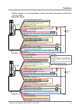
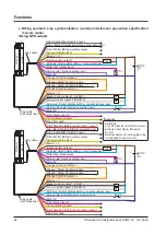
Wiring example: Line synchronization / standard specification (12-core cable)
<Using PNP output>
Emitter
Receiver
K1
K2
+ 24V DC
+20
-30
%
-
Gray cable
Gray cable
(with black line)
(Brown) + V
(Brown) + V
(Pale purple) Interlock setting input
(Gray / Black) Application indicator input 2
(Gray) Application indicator input 1
(Pink) Test / Reset input
(Red / White) Muting auxiliary output
(Red) Auxiliary output 1
(Pale blue) Output polarity setting / Lockout release input
(Yellow) Override input
(Pale blue) Output polarity setting / Lockout release input
(Red) Auxiliary output 2
(Gray) NC
(Blue) 0V
(Blue) 0V
(Orange) Synchroni
(Pale purple) External device monitor input
(Black) Control output 1 (OSSD 1)
(Pink) Muting input A
(White) Control output 2 (OSSD 2)
(Yellow) Muting input B
(Orange) Synchroni
(Orange / Black) Synchronization -
(Orange / Black) Synchronization -
*S1
Load
K1 K2
*Symbols
Switch S1
Vs to Vs-2.5V (source current 5mA or less): Emission halt (Note), Open: Emission
K1, K2: External device (forcible guide relay or magnetic conductor), etc.
Note: Vs is the supply voltage.
Summary of Contents for SF4D-TM1
Page 2: ... Panasonic Industrial Devices SUNX Co Ltd 2020 2 MEMO ...
Page 26: ...Procedures for Operation Panasonic Industrial Devices SUNX Co Ltd 2020 26 MEMO ...
Page 50: ...Software Tool Panasonic Industrial Devices SUNX Co Ltd 2020 50 MEMO ...
Page 89: ... Panasonic Industrial Devices SUNX Co Ltd 2020 89 Chapter 6 Troubleshooting ...