


Slide 21
When the TV is plugged in:
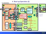
AC is applied to the standby circuit in the P board to produce STB5V.
The STB5V is provided to the A board via pin 5 of connector P6.
The STB5V from pin 10 of connector A6 is applied to the Analog ASIC (IC5000)
The Analog ASIC IC5000 converts the STB5V to STB3.3V.
This voltage energizes and prepares the microprocessor (CPU) IC8000 for program execution.
The STB3.3V from the Analog ASIC (IC5000), besides being applied to the CPU, is also applied to
the remote control receiver on the K board through pin 5 of connector A1/K10.
The microprocessor (IC8000) outputs the “F_STBY_ON” command for approximately 8 second.
This command is applied to the PSS for F15V generation. The F15V is generated for the same
duration of the command.
If the STB5V is missing, the TV is dead.
3. Standby Operation (6)
TC-P50/55/60/65ST60
Summary of Contents for S Series
Page 4: ...Slide 3 1 Board Layout and connectors Location ...
Page 10: ...Slide 9 2 Voltage Distribution ...
Page 16: ...Slide 15 3 Standby Operation ...
Page 23: ...Slide 22 4 Start up Operation ...
Page 29: ...Slide 28 5 SOS Detect Circuit Explanation Shutdown ...
Page 67: ...Slide 66 6 Blinking Code and No power Troubleshooting Flowchart ...
Page 91: ...Slide 90 Video Lines Troubleshooting ...
Page 95: ...Slide 94 Test Patterns ...
Page 96: ...Slide 95 Defective Panel Drive IC ...
Page 97: ...Slide 96 7 Electric pen and Bluetooth Troubleshooting Flowchart ...
Page 102: ...Slide 101 8 Wireless LAN adaptor Troubleshooting Flowchart ...
Page 106: ...Slide 105 9 Data Copy using USB Memory ...
Page 108: ...Slide 107 ...
Page 109: ...Slide 108 ...