


Slide 18
3. Standby Operation (3)
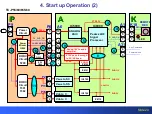
TC-P55/60/65S60
A
A
P
P
K
K
STB
Circuit
P6
A6
IC8000
Peaks sLD8
Signal
Processor
ANALOG
ASIC
A1
K10
5
10
REMOTE
REC.
STB5V
P9
IC5000
STB
3.3V
Control Assay
5
5
C1
C1
C14
C10
A31
1
1
9
F_STBY_ON
6
RMIN
KEY
KEYSCAN
C2
C2
C20
C21
5
4
3
2
39
40
2
1
51
52
Key
Command
POWER
SWITCH
Summary of Contents for S Series
Page 4: ...Slide 3 1 Board Layout and connectors Location ...
Page 10: ...Slide 9 2 Voltage Distribution ...
Page 16: ...Slide 15 3 Standby Operation ...
Page 23: ...Slide 22 4 Start up Operation ...
Page 29: ...Slide 28 5 SOS Detect Circuit Explanation Shutdown ...
Page 67: ...Slide 66 6 Blinking Code and No power Troubleshooting Flowchart ...
Page 91: ...Slide 90 Video Lines Troubleshooting ...
Page 95: ...Slide 94 Test Patterns ...
Page 96: ...Slide 95 Defective Panel Drive IC ...
Page 97: ...Slide 96 7 Electric pen and Bluetooth Troubleshooting Flowchart ...
Page 102: ...Slide 101 8 Wireless LAN adaptor Troubleshooting Flowchart ...
Page 106: ...Slide 105 9 Data Copy using USB Memory ...
Page 108: ...Slide 107 ...
Page 109: ...Slide 108 ...