Panasonic RG-T810LA Installation Instructions Manual Download Page 3

Do not install this ventilating fan in a location where the interior room 
temperature may exceed 104 °F (40 °C). 

Protect the supply wiring from sharp edges, oil, grease, hot surfaces, 
chemicals or other objects. 

Do not kink the supply wiring.

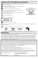
Not for use in cooking area. (Fig. A)

The special-purpose or dedicated parts, such as mounting fixtures, 
must be used if such parts are provided. 

For general ventilating use only. Do not use to exhaust hazardous or 
explosive materials and vapors.

Floor

45

°

45°

Cooking

equipment

Fig. A

(Cooking area)

Do not install above or

inside this area

Provide make up air for proper ventilation.

Do not connect multiple units in parallel. If two or more units are connected to one switch in parallel, the units 
may not function. 

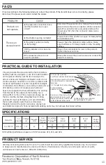
Do not install the unit where ducts are configured as shown in below:

Bend close to duct adaptor

Squeezed duct

Successive bending

Excessive bending

Adaptor

These products use a sirocco fan driven by a DC motor powered by an integral transformer. The motor is designed to
have a long operating life, high dynamic response, higher speed ranges and saving energy. The grille covering the fan 
body is a spring-loaded, quick removal type. A damper for preventing air counter flow is provided. The blower uses
a high-capacity sirocco fan developed to reduce the noise level. The lighting unit is an energy-saving LED lighting 
device that uses one 10 W LED lamp and produces almost the same illumination as a standard 40 W incandescent 
lamp. Night light feature consumes around 0.1 to 0.4 W.       

These products are listed by UL under UL file No. E78414.

FCC Note: This equipment has been tested and found to comply with the limits for a Class B digital device, pursuant 

to Part 15B of the FCC Rules. These limits are designed to provide reasonable protection against harmful interference 

in a residential installation. This equipment generates, uses and can radiate radio frequency energy and, if not installed 

and used in accordance with the instructions, may cause harmful interference to radio communications. However, 

there is no guarantee that interference will not occur in a particular installation. If this equipment does cause harmful 

interference to radio or television reception, which can be determined by turning this product on and off, the user is 

encouraged to try to correct the interference by one of the following measures:      

 SDoC Responsible Party:

                                                   Two Riverfront Plaza, Newark, NJ 07102

               1-866-292-7299

Reorient or relocate the receiving antenna.
Increase the separation between the equipment and receiver.

Consult the dealer or an experienced radio/TV technician for help.

Panasonic Corporation of North America

Connect equipment into outlet on a circuit different from that to which the receiver is connected. 

Warning: This equipment must be installed by a qualified person in accordance with the provided installation

instructions; and all applicable codes and standards. Also, any changes or modifications not expressly approved by

the party responsible for compliance could void the user’s authority to operate this equipment.

 Customer Call Center:

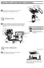
Please wear gloves to protect hands during installation. 

3

GENERAL SAFETY INFORMATION (CONTINUED)

DESCRIPTION

Summary of Contents for RG-T810LA

Page 1: ... of life electric shock fire malfunction and damage to equipment or property always observe the following safety precautions WARNING CAUTION Denotes a potential hazard that could result in serious injury or death Denotes a hazard that could result in minor injury Denotes a hazard that could result in property damage The following symbols are used to classify and describe the type of instructions t...

Page 2: ... Ducted exhaust fans must always be vented to the outdoors Make sure that the electric service supply voltage is AC 120 V 60 Hz Follow all local electrical and safety codes as well as the National Electrical Code NEC and the Occupational Safety and Health Administration OSHA CAUTION Always disconnect the power source before working on or near the fan motor light fixture or junction box These model...

Page 3: ...nsumes around 0 1 to 0 4 W These products are listed by UL under UL file No E78414 FCC Note This equipment has been tested and found to comply with the limits for a Class B digital device pursuant to Part 15B of the FCC Rules These limits are designed to provide reasonable protection against harmful interference in a residential installation This equipment generates uses and can radiate radio freq...

Page 4: ...nd carefully remove the unit from carton Refer to the Supplied Accessories list to verify that all parts are present 5 1 for spare Grille Long screw ST4 2X30 Installation instructions Warranty sheet No No Part name Part name PCB box Blower assy Blade Pick A Flow switch LED lamp Grille Adaptor Junction box Connector plate Damper Suspension bracket Fan body 4 DESCRIPTION CONTINUED UNPACKING SUPPLIED...

Page 5: ...y efficient than the minimum ENERGY STAR requirements These products employ innovative state of the art technologies that provide a number of customizable unique features that lead to improved indoor air quality Please read this manual first in order to realize the benefits of this customizable modular fan 5 Night Light Pick A Flow switch Air volume option CFM 80 100 80 CFM Factory setting This pr...

Page 6: ...circular exhaust duct to fit the adaptor then slip it onto adaptor and secure it with clamps or ties and seal it with mastic or approved foil tape 4 inch Squeeze Note If using 3 inch round duct please purchase the 26 gauge steel Panasonic 4 Oval 3 Round reducer from our representative Open knock out hole 1 Before installation please remove the tape which protects the damper during shipping and acc...

Page 7: ... wires Mount junction box cover carefully so that lead wires are not pinched Finish ceiling work Ceiling hole should be aligned with the inside edge of the flange Connect wires 3 Adaptor Junction box cover Knock out hole Circular duct Mastic or approved foil tape 3 1 Finish ceiling work 1 Unit inches mm After finishing the ceiling job fill gap between flange and ceiling with caulk or other sealant...

Page 8: ...p 2 and 3 of INSTALLATION I P 6 7 Insert one mounting spring into slot If not the grille may not be installed Connect the LED lamp wire to fan body Adjust Pick A Flow switch Refer to explanation under FEATURES Page 5 2 3 4 Slot Mounting spring Pick A Flow switch LED lamp wire 3 2 4 Install grille Drywall Mounting spring Gloves Grille 1 Insert the mounting springs into the slot as shown to mount gr...

Page 9: ...not immerse motor or LED lamp in water when cleaning Do not soak resin parts in water over 140 F 60 C Routine maintenance must be done every year Please wear gloves during the cleaning work Disconnect power supply before working on unit 9 After finishing the wall job fill gap between flange and wall with caulk or other sealant to prevent air leakage INSTALLATION II WALL MOUNTING CONTINUED MAINTENA...

Page 10: ...chen detergent remove any dirt from fan body Wipe dry with a clean cloth Reinstall grille after finishing NOTE The grille should be dry after cleaning 3 2 1 Clean grille Don t put into water Use non abrasive kitchen detergent wipe dry with a clean cloth Remove dust and dirt from fan body using a vacuum cleaner Gloves Drywall 2 Vacuum cleaner Drywall 3 Gloves 10 MAINTENANCE CLEANING Slot Mounting s...

Page 11: ... box to drywall Short piece of flexible duct helps alignment and absorbs sound Clamps plus mastic or approved foil faced tape at all flex joints Insulation Foil tape tightly covers all metal duct joints glue PVC joints Check according to the following table and correct the problem If the fan still does not work correctly please disconnect the power source and contact the dealer PROBLEM CAUSE ACTIO...

Page 12: ...an implied warranty lasts so the above exclusions or limitation may not apply to you Obtain Product Information and Operating Assistance locate your nearest distributor or make Customer Service and Literature requests by visiting our Web Site at us panasonic com ventfans or send your request by E mail to ventfans us panasonic com You may also contact us directly at 1 866 292 7299 Monday Friday 9 a...

Reviews: