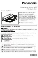


Warning Concerning Removal of Covers. The unit should be serviced by qualified technicians only. Your product
is designed and manufactured to ensure a minimum of maintenance. Should your unit require service or parts,
call Panasonic Call Center at 1-866-292-7299 (USA).
11
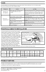
Properly insulate the area around the fan to minimize
building heat loss and gain. Loose fill or batt insulation
can be placed directly over the fan housing in the
attic. Our fans and fan/light combination units do not
create excessive heat that is a common problem with
recessed light fixtures or some competitor’s fan/light
combination. Our efficient, cool-running motors and our
LED lighting unit do not create enough ambient
heat to be subjected to these limitations. The ducting
from this fan to the outside of the building has a
strong effect on the air flow, noise and energy use of
the fan. Use the shortest, straightest duct routing
possible for best performance, and avoid installing
the fan with smaller ducts than recommended.
Insulation around the ducts can reduce energy loss
and inhibit mold growth. Fans installed with existing ducts may not achieve their rated air flow.
4 inch roof jack, wall cap,
or soffit vent with backdraft damper
Mechanically connect duct to termination
and seal with mastic or approved foil
faced tape
2-3 ft straight run before elbow
In attic installation,
caulk box to drywall
Short piece of flexible duct helps
alignment and absorbs sound.
Clamps plus mastic or approved
foil faced tape at all flex joints
Insulation
Foil tape tightly covers all metal
duct joints (glue PVC joints)
Check according to the following table and correct the problem. If the fan still does not work correctly, please
disconnect the power source and contact the dealer.
PROBLEM
CAUSE
ACTION
Product can
not operate.
Is the lead wire connection loose
and that resulted in an open
circuit?
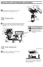
Disconnect the power source, remove the connector
plate to check the wire connection. (If the connector
plate (P.4) cannot be removed, please remove the
blower assy first, then the connector plate can be
removed).
There is an
ususual sound
Is the shutter opening normally?
Is the grille mounted correctly
on the ceiling?
Did the installed screw become
loose?
If the measures above do not
solve the problem...
Please check if the shutter can open normally before
the installation (P.6)
Please check the grille and ceiling surface, make
sure that there is no foreign matter on the mounting
surface.
Please check all installed screws in the product.
Tighten the loosened one.
Please disconnect the power source and contact the
dealer for servicing.
HVI Certified performance based on HVI Procedures 915, 916, and 920.
SPECIFICATIONS
FAQ’S
PRACTICAL GUIDE TO INSTALLATION
PRODUCT SERVICE
Model No.
Air
direction
Voltage
(V)
Frequency
(Hz)
Duct
diameter
(inches)
Air volume
at 0.1” WG
(CFM)
Noise
(sones)
Speed
(rpm)
Power
(W)
Weight
lb. (k )
Exhaust
80
100
0.5
1.1
881
993
8.9
13.2
7.9 (3.6)
RG-T810LA
120
60
4


