25
Camera
Special Effect Features
MagicVu allows you to record video in total
darkness. You can select the color of
image: B/W, green, or blue.
(Menu OSD: p. 102)
MagicVu IR Filter (0 Lux)
(PV-DV402 only)
2
MAGICVU/
0LUX
1
Set POWER to CAMERA.
2
Slide MAGICVU/0LUX to ON.
• A black and white image appears.
• “MAGICVU” will appear on the
screen.
3
Press MENU to display the menu
screen.
4
Rotate JOG KEY to select
SET-UP
,
and then press JOG KEY to display
the CAMERA SET-UP menu screen.
5
Rotate JOG KEY to select
MAGICVU
,
and then press JOG KEY repeatedly
to select B/W, BLUE, or GREEN.
• Press MENU twice to exit.
• To cancel this feature, slide
MAGICVU/0LUX to OFF.
• The subject can be up to 3 m (10 feet)
away.
Note
4, 5
JOG
KEY
3
MENU
1
POWER
1, 3, A
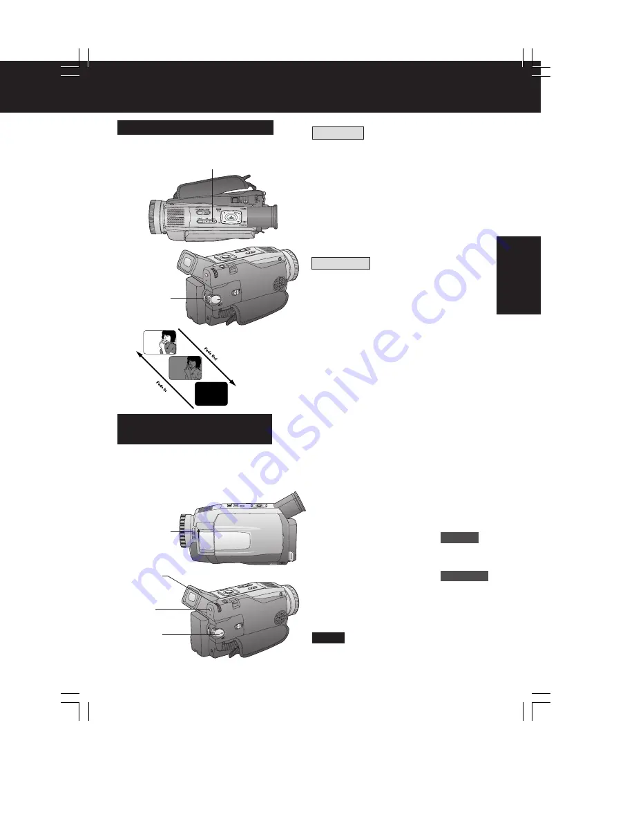
FADE
Audio/Video Fade In/Out
2, B
REC/
PAUSE
Fade In
Starting the first scene with “fade in” is very
effective.
1
In REC/PAUSE mode, hold down
FADE until the picture fades out.
2
Press REC/PAUSE to start
recording.
3
Release FADE and the picture will
gradually fade in.
Fade Out
Use to create a soft ending or (together
with fade in) for a soft transition from one
scene to the next.
A
During recording, hold down FADE
until the picture fades out.
B
Press REC/PAUSE to pause the
recording.
You can make smoother scene transitions
for a more professional look.
DV202_402PN.p 23-27.p65
02/02/13, 17:52
25
Summary of Contents for PV-DV102PN
Page 11: ...11 ...
Page 12: ...12 ...
Page 13: ...13 ...
Page 18: ...4 P C B Holder Fig 8 1 Fig 8 2 4 1 11 2 REMOVAL OF CSP IC Fig 8 3 18 ...
Page 19: ...4 1 11 3 INSTALLATION OF CSP IC Fig 8 4 19 ...
Page 20: ...Fig 8 5 20 ...
Page 21: ...4 1 11 4 CSP IC LOCATION Fig 8 6 21 ...
Page 27: ...5 2 1 Inner Parts Location 5 2 1 1 TOP VIEW Fig DM1 1 27 ...
Page 28: ...5 2 1 2 BOTTOM VIEW Fig DM1 2 28 ...
Page 30: ...5 2 3 Mechanism Base Unit Fig DM3 30 ...
Page 31: ...5 2 4 Guide Piece L Guide Piece R Garage Unit Fig DM4 31 ...
Page 32: ...5 2 5 Cylinder Unit Fig DM5 32 ...
Page 33: ...5 2 6 Dumper Unit Fig DM6 33 ...
Page 34: ...5 2 7 DEW Sensor DEW Cable Fig DM7 34 ...
Page 35: ...5 2 8 Mechanism F P C Unit Fig DM8 35 ...
Page 36: ...5 2 9 Reduction Gear B Fig DM9 36 ...
Page 37: ...5 2 10 Mechanism Cover Unit Fig DM10 37 ...
Page 38: ...5 2 11 Idler Arm Unit Center Gear Fig DM11 38 ...
Page 39: ...5 2 12 Tension Arm Unit Fig DM12 39 ...
Page 40: ...5 2 13 S Reel Table T Reel Table Fig DM13 40 ...
Page 41: ...5 2 14 T Break Unit Fig DM15 41 ...
Page 42: ...5 2 15 Pinch Arm Unit Fig DM16 42 ...
Page 43: ...5 2 16 Rail Fig DM17 43 ...
Page 44: ...5 2 17 Cylinder Base Unit Fig DM18 44 ...
Page 45: ...5 2 18 S T Arm Unit S T Post Unit Fig DM19 45 ...
Page 46: ...5 2 19 Loading Motor Unit Fig DM20 46 ...
Page 47: ...5 2 20 Sensor F P C Fig DM21 47 ...
Page 48: ...5 2 21 Tension Drive Arm S Brake Drive Lever Fig DM22 48 ...
Page 49: ...5 2 22 Cam Gear Fig DM23 49 ...
Page 50: ...5 2 23 Pinch Drive Arm Intermediate Gear Fig DM24 50 ...
Page 51: ...5 2 24 Mode Switch Fig DM25 51 ...
Page 52: ...5 2 25 MIC Switch Fig DM26 52 ...
Page 53: ...5 2 26 Main Plate Unit Fig DM27 53 ...
Page 54: ...5 2 27 T4 Drive Arm Fig DM28 54 ...
Page 55: ...5 2 28 Drive Pulley Fig DM29 55 ...
Page 56: ...5 2 29 Capstan Unit Timing Belt Capstan Adjust Spring Fig DM30 56 ...
Page 57: ...5 2 30 Lock Lever Unit Lock Pick Lever Fig DM31 57 ...
Page 58: ...6 ADJUSTMENT PROCEDURES 6 1 SERVICE FIXTURES TOOLS 58 ...
Page 59: ...59 ...
Page 72: ...10 2 FRONT CASE SECTION 72 ...
Page 73: ...10 3 CCD AND LENS SECTION 73 ...
Page 74: ...10 4 TOP CASE AND EVF SECTION 74 ...
Page 75: ...10 5 SIDE CASE R AND LCD SECTION Model PV DV102 PV DV202 75 ...
Page 76: ... Model PV DV402 76 ...
Page 77: ...10 6 MECHANISM SECTION 77 ...
Page 78: ...10 7 PACKING PARTS AND ACCESSORIES SECTION 78 ...
Page 89: ...285 LSGB0031 MULTIMEDIA CARD BADGE 1 89 ...
Page 165: ......


