


Chapter 7
Appendix — Specifications
204 - ENGLISH
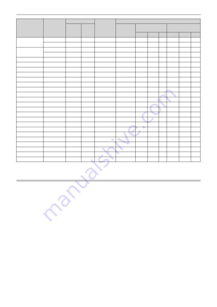
Signal name
(SIGNAL FORMAT)
Resolution
(Dots)
Scanning freq.
Dot clock
freq.
(MHz)
Plug and play compatible signal
Horizontal
(kHz)
Vertical
(Hz)
COMPUTER
HDMI
DIGITAL LINK
4K/60P 4K/30P 2K 4K/60P 4K/30P 2K
4096 x 2160/60p
4 096 x 2 160
135.0
60.0
*2
297.0
―
l
*3
―
―
l
*3
―
―
4 096 x 2 160
135.0
60.0
*2
594.0
―
l
―
―
―
―
―
4096 x 2160/50p
4 096 x 2 160
112.5
50.0
297.0
―
l
*3
―
―
l
*3
―
―
4 096 x 2 160
112.5
50.0
594.0
―
l
―
―
―
―
―
640 x 480/60
640 x 480
31.5
59.9
25.2
l
l
l
l
l
l
l
1024 x 768/50
1 024 x 768
39.6
50.0
51.9
―
―
―
―
―
―
―
1024 x 768/60
1 024 x 768
48.4
60.0
65.0
l
l
l
l
l
l
l
1280 x 800/50
1 280 x 800
41.3
50.0
68.0
―
―
―
―
―
―
―
1280 x 800/60
1 280 x 800
49.7
59.8
83.5
―
―
―
―
―
―
―
1280 x 1024/50
1 280 x 1 024
52.4
50.0
88.0
―
―
―
―
―
―
―
1280 x 1024/60
1 280 x 1 024
64.0
60.0
108.0
―
―
―
―
―
―
―
1366 x 768/50
1 366 x 768
39.6
49.9
69.0
―
―
―
―
―
―
―
1366 x 768/60
1 366 x 768
47.7
59.8
85.5
―
―
―
―
―
―
―
1400 x 1050/50
1 400 x 1 050
54.1
50.0
99.9
―
―
―
―
―
―
―
1400 x 1050/60
1 400 x 1 050
65.2
60.0
122.6
l
l
l
l
l
l
l
1440 x 900/50
1 440 x 900
46.3
49.9
86.8
―
―
―
―
―
―
―
1440 x 900/60
1 440 x 900
55.9
59.9
106.5
―
―
―
―
―
―
―
1600 x 900/50
1 600 x 900
46.4
49.9
96.5
―
―
―
―
―
―
―
1600 x 900/60
1 600 x 900
55.9
60.0
119.0
l
l
l
l
l
l
l
1600 x 1200/50
1 600 x 1 200
61.8
49.9
131.5
―
―
―
―
―
―
―
1600 x 1200/60
1 600 x 1 200
75.0
60.0
162.0
l
l
l
l
l
l
l
1680 x 1050/50
1 680 x 1 050
54.1
50.0
119.5
―
―
―
―
―
―
―
1680 x 1050/60
1 680 x 1 050
65.3
60.0
146.3
―
―
―
―
―
―
―
1920 x 1200/50
1 920 x 1 200
61.8
49.9
158.3
―
―
―
―
―
―
―
1920 x 1200/60RB
1 920 x 1 200
*1
74.0
60.0
154.0
l
l
l
l
l
l
l
*1
VESA CVT-RB (Reduced Blanking)-compliant
*2
The signal with 1/1.001x vertical scanning frequency is also supported.
*3
YP
B
P
R
4:2:0 format only
Note
f
A signal with a different resolution is converted to the number of display dots. The number of display dots is as follows.
g
1 920 x 1 200
f
The “i” at the end of the resolution indicates an interlaced signal.
f
When interlaced signals are connected, flickering may occur on the projected image.
f
When the DIGITAL LINK connection is made with the long-reach communication method, the signal that the projector can receive is up to
1080/60p (1 920 x 1 080 dots, dot clock frequency 148.5 MHz).
f
Even if it is the signal listed in the list of compatible signals, it may not be displayed by the projector if the video signal is recorded in a
special format.


