capacitor, between each exposed metallic part on the set and a
good earth ground , as shown in Figure 1.
3. Use an AC voltmeter, with 1 k /V or more sensitivity, to measure
the potential across the resistor.
4. Check each exposed metallic part, and measure the voltage at
each point.
5. Reverse the AC plug in the AC outlet and repeat each of the above
measurements.
6. The potential at any point should not exceed 0.75 V RMS.
A leakage current tester (Simpson Model 229 equivalent) may be
used to make the hot checks. Leakage current must not exceed 1/
2 mA. In case a measurement is outside of the limits specified,
there is a possibility of shock hazard, and thereceiver should be
repaired and rechecked before it is returned to the customer.
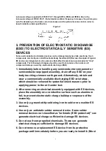
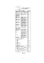
Figure 1
2. X-RADIATION
WARNING :
1. The potential source of X-Radiation in TV sets is the High Voltage
section and the picture tube.
2. When using a picture tube test fixture for service, ensure that the
fixture is capable of handling 25.0 kV (For model with 13 inch
CRT) or 30.0 kV (For model with 20 inch CRT) without causing X-
Radiation.
NOTE :
It is important to use an accurate periodically calibrated high
voltage meter.
1. Reduce the brightness to minimum.
5
Summary of Contents for OmniVision PV-C1324-K
Page 10: ...Fig 1 4 Fig 1 5 10 ...
Page 11: ...Fig 1 6 11 ...
Page 19: ...6 1 2 Disassembly Method Fig D2 19 ...
Page 20: ...Fig D3 20 ...
Page 21: ...6 1 2 1 Notes in chart 1 Removal of VCR Unit Fig D4 21 ...
Page 39: ...39 ...
Page 41: ...11 2 CHASSIS FRAME SECTION 1 41 ...
Page 42: ...11 3 CHASSIS FRAME SECTION 2 42 ...
Page 43: ...11 4 PACKING PARTS AND ACCESSORIES SECTION 43 ...
Page 60: ...R6079 ERJ6GEYJ102V MGF CHIP 1 10W 1K 60 ...
Page 65: ...C3035 ECJ2VC1H330J C CHIP 50V 33PF 65 ...
Page 74: ...13 2 CHASSIS FRAME SECTION 1 74 ...
Page 75: ...13 3 CHASSIS FRAME SECTION 2 75 ...
Page 76: ...13 4 PACKING PARTS AND ACCESSORIES SECTION 76 ...
Page 89: ...R554 ERDS2TJ123 CARBON 1 4W 12K 89 ...


