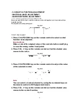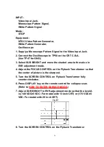
5. Press CH UP/DOWN key on the remote control to select a control
function for the next adjustment if necessary.
Fig. E2-5
7.3.3.2.2. How to release from EVR Adjustment Mode:
Press and hold STOP, PLAY, and VOL- buttons on the unit together over 5 seconds again or
press the POWER button OFF to release EVR adjustment mode. The adjusted value will be
written to Memory IC (IC6004).
7.3.3.3. HOW TO ENTER SERVICE MODE
1. Enter EVR adjustment mode.
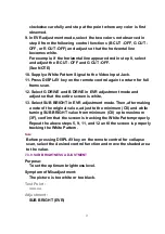
2. Press DISPLAY key on the remote control for collapse scan.
Note:
Before pressing DISPLAY key on the remote control for collapse
scan, select the desired control function and move the shaded
area to the value for adjustments you will proceed.
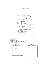
Fig. E2-6
7.3.3.3.1. How to release from Service Mode:
Press DISPLAY key again on the remote control.
7.3.4. SUB CONTRAST ADJUSTMENT
Purpose:
To set the optimum sub contrast level.
Symptom of Misadjustment:
The picture is too dark or too light.
Test Point :
Pin 5 of P6001 (TV/VCR Main C.B.A.) or TP49 (CRT C.B.A.)
Adjustment :
27
Summary of Contents for OmniVision PV-C1324-K
Page 10: ...Fig 1 4 Fig 1 5 10 ...
Page 11: ...Fig 1 6 11 ...
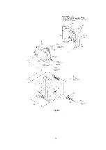
Page 19: ...6 1 2 Disassembly Method Fig D2 19 ...
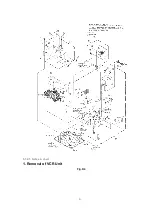
Page 20: ...Fig D3 20 ...
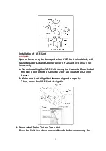
Page 21: ...6 1 2 1 Notes in chart 1 Removal of VCR Unit Fig D4 21 ...
Page 39: ...39 ...
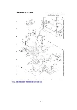
Page 41: ...11 2 CHASSIS FRAME SECTION 1 41 ...
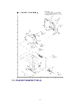
Page 42: ...11 3 CHASSIS FRAME SECTION 2 42 ...
Page 43: ...11 4 PACKING PARTS AND ACCESSORIES SECTION 43 ...
Page 60: ...R6079 ERJ6GEYJ102V MGF CHIP 1 10W 1K 60 ...
Page 65: ...C3035 ECJ2VC1H330J C CHIP 50V 33PF 65 ...
Page 74: ...13 2 CHASSIS FRAME SECTION 1 74 ...
Page 75: ...13 3 CHASSIS FRAME SECTION 2 75 ...
Page 76: ...13 4 PACKING PARTS AND ACCESSORIES SECTION 76 ...
Page 89: ...R554 ERDS2TJ123 CARBON 1 4W 12K 89 ...

