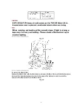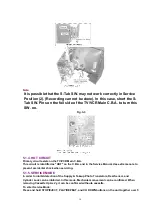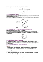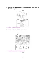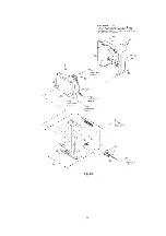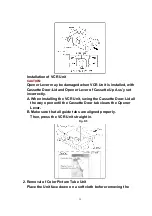
Color Picture Tube Unit.
3. Installation of Mechanism Chassis and Cassette Up Ass’y onto
Main C.B.A.
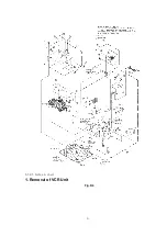
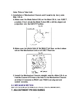
A. Make sure the Mode Select SW. on the Main C.B.A. is in EJECT
position. If not, rotate the Mode Select SW. until the alignment
projection is in the EJECT Position.
Fig. D6
B. Make sure the phase hole of the Main Cam Gear on the bottom
side of the Mechanism Unit is in EJECT Position.
Fig. D9
C. Install the Mechanism Chassis straight onto the Main C.B.A. so
that the Sensor LED clears the hole in the Mechanism Chassis
and that 2 Connectors (P6201 and P4001) are aligned and
seated securely.
6.2. MECHANISM SECTION
Refer to the Service Manual for R4-Mechanism Chassis. (Order No. MKE0401000C1)
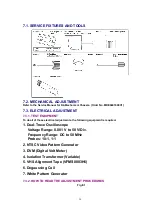
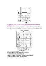
7. ADJUSTMENT PROCEDURES
23
Summary of Contents for OmniVision PV-C1324-K
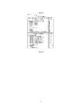
Page 10: ...Fig 1 4 Fig 1 5 10 ...
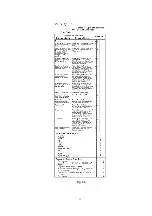
Page 11: ...Fig 1 6 11 ...
Page 19: ...6 1 2 Disassembly Method Fig D2 19 ...
Page 20: ...Fig D3 20 ...
Page 21: ...6 1 2 1 Notes in chart 1 Removal of VCR Unit Fig D4 21 ...
Page 39: ...39 ...
Page 41: ...11 2 CHASSIS FRAME SECTION 1 41 ...
Page 42: ...11 3 CHASSIS FRAME SECTION 2 42 ...
Page 43: ...11 4 PACKING PARTS AND ACCESSORIES SECTION 43 ...
Page 60: ...R6079 ERJ6GEYJ102V MGF CHIP 1 10W 1K 60 ...
Page 65: ...C3035 ECJ2VC1H330J C CHIP 50V 33PF 65 ...
Page 74: ...13 2 CHASSIS FRAME SECTION 1 74 ...
Page 75: ...13 3 CHASSIS FRAME SECTION 2 75 ...
Page 76: ...13 4 PACKING PARTS AND ACCESSORIES SECTION 76 ...
Page 89: ...R554 ERDS2TJ123 CARBON 1 4W 12K 89 ...

