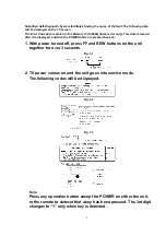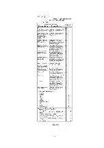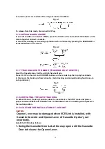
seconds in power on condition.The unit goes into Service Mode.
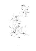
Fig. 4-1
To release from this mode, disconnect AC Plug.
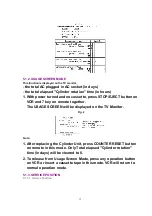
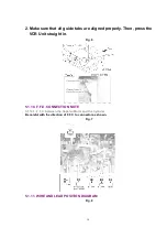
5.1.6. MECHA MANUAL MODE
In shut off condition or in Service Mode, press the CH UP on the unit and CH UP buttons on the
remote together without a cassette.
In this mode, Loading or Unloading operation can be confirmed by pressing the REW/SLOW or
FF/SLOW button on the remote.
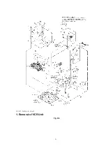
Fig. 4-2
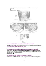
5.1.7. TRACKING CENTER MODE (TRACKING FIX AT CENTER)
Insert the Cassette tape. Set the unit into Service Mode.
Press CH UP on the unit and CH DOWN buttons on the remote together in play back mode.
In this mode, the tracking is fixed at center. (Auto tracking and manual tracking functions are
not operational.)
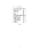
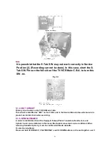
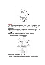
Fig. 5
5.1.8. DEFEATING THE AUTO TRACKING
To defeat the Auto Tracking Function, place the instrument in the STOP mode and place a
jumper between TP6003 and TP6009 on the TV/VCR Main C.B.A. The tracking will be placed in
the neutral position.
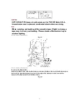
5.1.9. CAUTION FOR INSTALLATION OF VCR UNIT
CAUTION:
Opener Lever may be damaged when VCR Unit is installed, with
Cassette Door-Lid and Opener Lever of Cassette Up Ass’y set
incorrectly.
Install the VCR Unit as follows:
1. Swing the Cassette Door-Lid all the way open until the Cassette
Door tab clears the Opener Lever.
15
Summary of Contents for OmniVision PV-C1324-K
Page 10: ...Fig 1 4 Fig 1 5 10 ...
Page 11: ...Fig 1 6 11 ...
Page 19: ...6 1 2 Disassembly Method Fig D2 19 ...
Page 20: ...Fig D3 20 ...
Page 21: ...6 1 2 1 Notes in chart 1 Removal of VCR Unit Fig D4 21 ...
Page 39: ...39 ...
Page 41: ...11 2 CHASSIS FRAME SECTION 1 41 ...
Page 42: ...11 3 CHASSIS FRAME SECTION 2 42 ...
Page 43: ...11 4 PACKING PARTS AND ACCESSORIES SECTION 43 ...
Page 60: ...R6079 ERJ6GEYJ102V MGF CHIP 1 10W 1K 60 ...
Page 65: ...C3035 ECJ2VC1H330J C CHIP 50V 33PF 65 ...
Page 74: ...13 2 CHASSIS FRAME SECTION 1 74 ...
Page 75: ...13 3 CHASSIS FRAME SECTION 2 75 ...
Page 76: ...13 4 PACKING PARTS AND ACCESSORIES SECTION 76 ...
Page 89: ...R554 ERDS2TJ123 CARBON 1 4W 12K 89 ...


