No. SX-DSV02829 -
26-
Pr 7.00
Information on
display
Remarks
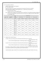
8
Pole position
estimated accuracy
The estimated accuracy is shown as 0 to B4 [hex] (electric angle: 0 to 180 [degree]) when estimating a
pole position
Example: When the display is ‘ A’:
It means that the pole position estimated accuracy is up to ±10 [degree] in electric angle.
▪
The smaller this numeric value is, the better the accuracy is.
▪
This accuracy is an estimated accuracy based on the pole position estimation method and will not
guarantee a real accuracy. Use it only for reference.
▪
When the pole position is not yet estimated, ‘ 0’ is shown.
▪
When estimating the pole position, ‘b4’ is shown.
▪
When an error occurs in estimating the pole position, ‘b4’ is shown.
▪
If Pr9.20 “Pole detection method”
≠
2 (other than pole position estimation), ‘ 0’ is shown.
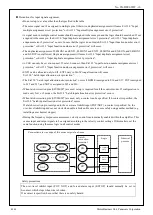
9
CS signal,
operation direction
If Pr9.20 “Pole detection method” = 1 (CS signal), the CS signal status is shown at the right and the
operation direction is shown at the left.
CS signal status
CS1, 2, 3 are shown from the top downward, ‘–’ is shown for ON, and nothing is shown for OFF.
Note that the CS signal is shown with Pr3.26 (signal (original signal) before the inversion
process).
Operation direction
The upper left LED lights up when running (speed is 30 r/min or more) in a positive
direction
The lower left LED lights up when running (speed is -30 r/min or less) in a negative
direction
The center LED lights up when it stops (otherwise).
When other than Pr9.20 = 1, ‘nA’ is shown.
Other
To be used by the
manufacturer but
not by the user.
—
For CS1=ON
For CS2=ON
For CS3=ON
For a positive direction
For a stoppage
For a negative direction
R1.00
Motor Business Unit, Panasonic Corporation


