No. SX-DSV02829 -
181-
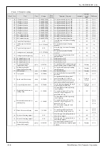
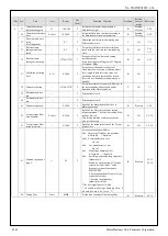
Class 5: Enhancing setting
Class No.
Title
Unit
Range
Size
[byte]
Function / Contents
Attribute
Related
control
mode
Reference
5
03
Denominator of pulse
output division
(Not supported)
—
0–
262144
4
Set up the denominator of pulse output
division.
R
All
4-2-5
04
Over-travel inhibit input
setup
—
0–2
2
Set up the operation of the inhibit positive/
negative direction travel inputs.
C
All
6-3-1
7-4
05
Sequence at over-travel
inhibit
—
0–2
2
Set up the sequence when over-travel inhibit
is input.
C
All
6-3-1
7-4
06 Sequence at Servo-Off
—
0–9
2
Set up the sequence while servo is OFF.
B
All
6-3-2
07
Sequence upon main
power off
—
0–9
2
Set up the sequence while main AC power is
OFF.
B
All
6-3-3
08
L/V trip selection upon
main power off
—
0–3
2
Select LV trip or servo OFF upon occurrence of
main AC power alarm.
Setup the condition to detect main AC power
OFF alarm when the main AC power is kept
interrupted for a time longer than the time set by
Pr7.14.
bit 0 0: Select servo OFF according to the
setting of Pr 5.07 and then return to
servo ON by turning ON main AC
power.
1: Trip with Err 13.1 Main power
undervoltage protection.
bit 1 0: Detect main AC power OFF alarm
only when servo is in ON state.
1: Always detect main AC power OFF
alarm.
B
All
6-3-3
09
Detection time of main
power off
1 ms
70–
2000
2
Set up main AC power alarm detection time.
Main AC power OFF detection is disabled
when the setting value is 2000.
Resolution of setting is 2 ms. For example,
when setting value is 99, processed in
100 ms.
C
All
6-3-3
10 Sequence at alarm
—
0–7
2
Set up the sequence used upon occurrence of
an alarm.
B
All
6-3-4
6-3-5
11
Torque setup for
emergency stop
%
0–500
2
Set up the torque limit at emergency stop.
When setup value is 0, the torque limit for
normal operation is applied.
B
All
6-3-1
6-3-2
6-3-3
6-3-5
12 Over-load level setup
%
0–500
2
You can set up the over-load level. It
becomes 115% by setting up this to 0.
The setup value of this parameter is limited
by 115% of the motor rating.
A
All
—
13 Over-speed level setup
r/min
0–
20000
2
Set up the detection level of Err.26.0
Over-speed protection. When the setting
value is 0, the over-speed is detected when
the speed is 1.2 times the motor max. speed.
The internal value is limited to the motor
max. speed
×
1.2.
A
All
6-3-5
14
Motor working range
setup
0.1
magnet
pitch
0–1000
2
Set up motor over-travel limit to the position
command.
A
Position
6-2
7-4
15
Control input signal
reading setup
—
0–3
2
Set up a read signal for cycle of the control
input.
0:0.250ms,1:0.500ms,2:1.500ms,3:2.500ms
However, with the exception of the external
latch input1/2(EXT1/2).
C
All
—
20 For manufacturer’s use
—
—
2
Permanently set at 0.
—
—
—
21 Selection of torque limit
—
1–4
2
Select positive direction or negative direction
torque limit. *1)
B
Position,
Velocity
6-1
22 2nd torque limit
%
0–500
2
You can set up the 2nd limit value of the
motor output torque.
In addition, the actual torque applied is
limited with the maximum torque limit for the
motor applied. (The parameter value is not
limited)
B
Position,
Velocity
6-1
25 For manufacturer’s use
—
—
2
Permanently set at 0.
—
—
—
26 For manufacturer’s use
—
—
2
Permanently set at 0.
—
—
—
29 For manufacturer’s use
—
—
2
Permanently set at 2.
—
—
—
31 USB axis address
—
0–127
2
Set up the axis number for USB
communication.
C
All
—
33
Pulse regenerative
output limit setup
(Not supported)
—
0–1
2
Enable/disable detection of Err 28.0 (Pulse
regenerative limit protection).
0: Invalid 1: Valid
C
All
4-2-5
34 For manufacturer’s use
—
—
2
Permanently set at 4.
―
—
—
*1) The count up direction of feedback scale always serves as positive.
R1.00
Motor Business Unit, Panasonic Corporation


