PRO4 Mode
8-1. PRO4 Mode Functions and Settings
8
PRO4 mode is mainly used for configuring communication with sub units and external input modes.
By utilizing the optical communications function, the settings information from the
operating amplifier can be copied to other connected amplifiers. (Except for data bank
contents) However, the 0-Adjust setting function and transmission change to permit /
not to permit function will not be copied. As well, in amplifiers in which the optical
communications settings change function has been locked, copying will not occur.
When attempting to perform single step load / save / copy operations using the
data bank load function and data bank save function from PRO3 mode, and copy
function from PRO4 mode, if the transmission change has not been permitted,
then only the specified amplifier will be locked. Therefore single step load / save /
copy operations will be disabled.
* The factory setting is ‘Lock OFF’.
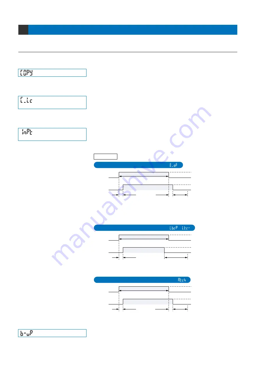
Selects ‘emission halt’, ‘full-auto teaching’ or ‘limit teaching’ using external input
wires.
Note: Output operations are undefined only for the response time.
When the output signal is being received by a PLC or other device, set the timer to 2 ms
sensor
response time or longer.
Example: For the response time in STD mode (500
!
s)
Timer period: 2 ms
0.5 ms (500
!
s)
2.5 ms
Signal conditions: High...
5 V to
V, or open (NPN type),
4 V to
V (PNP type)
Low...0 to
2 V (NPN type), 0 to
0.6 V, or open (PNP type)
Note: After teaching is finished, output operations are undefined only for the response time.
When the output signal is being received by a PLC or other device, set the timer to the sensor
response time or longer.
The incident light intensity at the instant teaching is recognized is set as the standard threshold value.
Notes: 1) Pass the sensing object past the sensor once while an input signal is being input.
2) After teaching is finished, output operations are undefined only for the response time.
When the output signal is being received by a PLC or other device, set the timer to the sensor
response time or longer.
This function is used for not storing the threshold value obtained from external
input teaching into the EEPROM.
It prevents unnecessary writing to the EEPROM.
* Note that when the power is turned off, the threshold value becomes the value
that was last stored in memory.
External input
High (NPN type: Low)
Low (NPN type: High)
High (NPN type: Low)
Low (NPN type: High)
High (NPN type: Low)
Low (NPN type: High)
During teaching
Normal operation
During teaching
Normal operation
Emission halt
Emission
3 ms or more
3 ms or more
3 ms or more (Note 1)
2 ms
2 ms
(Note)
Emission halt
Limit teaching
2 ms
2 ms
2 ms
External input
Full-auto teaching
(Note)
External input
In case of selecting emission halt ( )
Refer to p. 42 for setting procedure
Refer to p. 43 for setting procedure
Refer to p. 44 for setting procedure
Equipped with cable type only.
Refer to p. 45 for setting procedure
Equipped with cable type only.
: Copy Function
: Backup Function
: External Input Switch
Setting Function
: Selection for transmission
change to permit / not to permit
Time chart
In case of selecting limit teaching ( , )
In case of selecting full-auto teaching ( )
(Note 2)
41
Ramco National (800) 280-6933 www.pansonicsensors.com


