

83
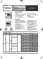
LC4H-S
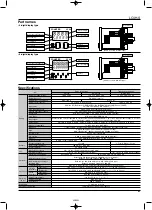
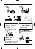
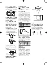
Part names
Specifications
Item
Ralay output type
AC type
100 to 240 V
DC/AC type
12 to 24 V DC/24 V AC
50/60 Hz common
Max. 10 V A
5 A 250 V AC (resistive load)
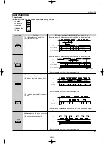
Addition (UP)/Subtraction (DOWN)/Direction (DIR)/Individuality (IND)/Phase (PHASE)
5 modes selectable by DIP switches
30 Hz, 5 kHz (selectable by DIP switches)
16.7 ms at 30 Hz/0.1 ms at 5 kHz ON time: OFF time = 1:1
Min. input signal width: 1 ms, 20 ms (selected by DIP switches)
Min. input signal width: 20 ms
Contact, Open collector input/DC two-wire system sensor Input impedance: 1 k
Ω
or less, Input residual voltage: 2 V or less,
Open impedance: 100 k
Ω
or less, Max. energized voltage: 40 V DC
HOLD-A, HOLD-B, HOLD-C, SHOT-A, SHOT-B, SHOT-C, SHOT-D, 7 modes selectable by DIP switches
1 s, 0.5s, 0.2s, 0.1s, 0.05, 0.01s
7-segment LCD, Counter value (backlight red LED), Setting value (backlight yellow LED)
4-digit display type –999 to 9999 (0 to 9999 for setting)
6-digit display type –99999 to 999999 (0 to 999999 for setting)
EEP-ROM (Overwriting times: 10
5
ope. or more)
12 V DC (±10%) 100 mA Max.
—
1 Form C
100 m
Ω
(at 1 A 6 V DC)
Ag alloy/Au flush
2.0
×
10
7
ope. (Except for switch operation parts)
1.0
×
10
5
ope. (At rated control voltage)
85 to 264 V AC
10.8 to 26.4 V DC, 20.4 to 26.4 V AC
Between live and dead metal parts: 2,000 Vrms for 1 min (pin type)
Between input and output: 2,000 Vrms for 1 min
Max. 65° C (under the flow of nominal operating current at nominal voltage)
10 to 55 Hz (1 cycle/min), single amplitude: 0.35 mm
.014 inch
(10 min on 3 axes)
10 to 55 Hz (1 cycle/min), single amplitude: 0.75 mm
.030 inch
(1 h on 3 axes)
1 Form A (Open collector)
—
—
—
1.0
×
10
7
ope. (At rated control voltage)
12 to 24 V DC/24 V AC
Max. 3 W
100 mA, 30 V DC
Transistor output type
DC/AC type
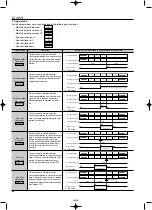
Rating
Contact
Life
Electrical
Mechanical
Operating
conditions
Rated operating voltage
Rated frequency
Rated power consumption
Rated control capacity
Input mode
Max. counting speed
Counting input (input 1, input 2)
Reset input
Lock input
Input signal
Output mode
One shot output time
Indication
Digit
Memory
0.001 to 9.999 (4-digit type), 0.001 to 99.999 (6-digit type)
Pre-scaling
Can be set to three digits
Decimal point
Power for senser
Contact arrangement
Initial contact resistance
Contact material
Mechanical (contact)
Electrical (contact)
Operating voltage range
Initial withstand voltage
Between live and dead metal parts: Min. 100 M
Ω
(pin type)
Between input and output: Min. 100 M
Ω
Initial insulation resistance
(At 500 V DC)
Temperature rise
Functional
Destructive
Vibration
resistance
Min. 98 m/s
2
(4 times on 3 axes)
Min. 294 m/s
2
(5 times on 3 axes)
–10° C to 55° C
+14° F to +131° F
Max. 85 % RH
860 to 1,060 h Pa
11-pin/screw terminal
IP66 (front panel with a rubber gasket)
Functional
Destructive
Ambient temperature
Ambient humidity
Air pressure
Connection
Protective construction
Shock
resistance
• 4-digit display type
• 6-digit display type
DOWN
UP
SET/ LOCK
RESET
L O C K
R S T
O P .
LC4H
COUNTER
ON
8
7
6
5
4
3
2
1
RESET
L O C K
R S T
O P .
LC4H
COUNTER
ON
8
7
6
5
4
3
2
1
SET/ LOCK
Controlled output indicator
Reset indicator
Lock indicator
Reset switch
Set/lock switch
Counter display
Set value display
Up keys
Down keys
DIP switches
(Same for screw terminal type)
Controlled output indicator
Reset indicator
Lock indicator
Reset switch
Set/lock switch
Counter display
Set value display
Up keys
DIP switches
(Same for screw terminal type)
02/2003


