

88
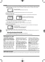
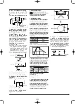
2. Output mode
For the output mode, you can choose one of the following seven modes
• Maintain output/hold count
• Maintain output/over count
I
• Maintain output/over count
II
• One shot/over count
• One shot/recount
I
• One shot/recount
II
• One shot/hold count
SHOT-D
SHOT-C
SHOT-B
SHOT-A
HOLD-C
HOLD-B
HOLD-A
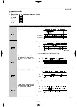
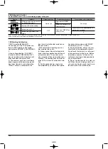
Output mode
Maintain output
Hold count
HOLD-A
Operation
(Example when input mode is either addition or subtraction)
Output control is maintained after
count-up completion and until resetting.
During that time, the count display does
not change from that at count-up com-
pletion.
* n: Set value
Maintain output
Over count
I
HOLD-B
Output control is maintained after
count-up completion and until resetting.
However, counting is possible despite
completion of count-up.
* n: Set value
Maintain output
Over count
II
HOLD-C
Output control is maintained after
count-up completion and until the next
signal enters. However, counting is
possible despite completion of count-
up.
* n: Set value
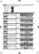
One shot
Over count
SHOT-A
Output control is maintained after
count-up completion for one shot output
time. Counting is possible despite com-
pletion of count-up.
* n: Set value
One shot
Recount
I
SHOT-B
Output control is maintained after
count-up completion for one shot output
time. Counting is possible despite com-
pletion of count-up. However, reset
occurs simultaneous with completion of
count-up. While output is being main-
tained, restarting of the count is not
possible
* n: Set value
One shot
Recount
II
SHOT-C
Output control is maintained after
count-up completion for one shot output
time. Counting is possible despite com-
pletion of count-up. However, reset
occurs simultaneous with output OFF.
* n: Set value
One shot
Hold count
SHOT-D
Output control is maintained after
count-up completion for one shot output
time. During that time, the count display
does not change from that at count-up
completion. Reset occurs simultaneous
with output OFF.
* n: Set value
Counting (addition)
Counting (subtraction)
Counting able/unable
Output control
OFF
ON
n-3
n-2
n-1
n
3
2
1
0
Able
Unable
n-2
n-1
n
n+2
n+1
2
1
0
-2
-1
Able
Counting (addition)
Counting (subtraction)
Counting able/unable
Output control
OFF
ON
n-2
n-1
n
n+2
n+1
2
1
0
-2
-1
Able
Counting (addition)
Counting (subtraction)
Counting able/unable
Output control
OFF
OFF
ON
n-2
n-1
n
n+2
n+1
2
1
0
-2
-1
Able
Counting (addition)
Counting (subtraction)
Counting able/unable
Output control
OFF
OFF
ON
Approx. 1s
n-2
n-1
0
2
1
2
1
n
n-2
n-1
Reset (automatic)
Able
Counting (addition)
Counting (subtraction)
Counting able/unable
Output control
OFF
OFF
ON
Approx. 1s
n-1
n
n+1
1
0
1
0
-1
n-1
n
Reset (automatic)
Able
Counting (addition)
Counting (subtraction)
Counting able/unable
Output control
OFF
OFF
ON
Approx. 1s
n-1
n
1
0
1
0
n-1
n
Reset (automatic)
Approx. 1s
Able
Able
Unable
Counting (addition)
Counting (subtraction)
Counting able/unable
Output control
OFF
OFF
ON
LC4H-S
02/2003


