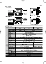
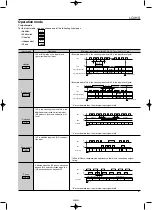
background image

100

Display

Contents

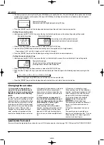
Minimum value went below –999
or –99999. See note 1.

Enter reset or RESET
key.
Restart unit (correct DIP
switch settings)

Enter reset, RESET key,
or restart unit.

No change

The values at start-up before the CPU
malfunction occurred.
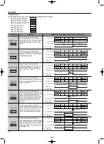
0

Incorrect DIP switch setting.

Malfunctioning CPU.

Malfunctioning memory. See
note 2.

No change

OFF

Output condition

Restoration procedure

Preset values after restoration

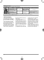
7. CE Marking Certification

1) EMC directive (89/336/EEC)
As a counter unit, the LC4H series con-
forms to EMC directives. Applicable
standards are EN50081-2 and EN50082-
2.
2) Low voltage directive (73/23/EEC)
In order to satisfy VDE0435/Part 2021,
be sure to adhere to the following instal-
lation conditions and precautions.
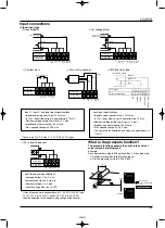
(1) The counter uses a non-transformer
power supply and the power supply and
input signal terminals are not insulated.
• When a sensor is connected to the

input circuit, install double insulation on
the sensor side.
• With contact-point inputting, use dou-
ble-insulated relays, etc.
(2) Always connect loads insulated with
basic insulation specifications to the out-
put contact points. The counter unit is
also insulated with basic insulation speci-
fications. The combination of the two sat-
isfies VDE, which calls for double insula-
tion.
(3) For the applied power supply, use
one protected by an over-current protec-

tion device that conforms with EN/IEC
standards (e.g. 250 V, 1 A fuse).
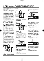
(4) During installation, always use a ter-
minal block or the appropriate sockets.
Do not touch the terminals, or other part
of the counter unit while it is on. Before
installation or removal of the unit, first
verify that no voltage is being applied to
any of the terminals.
(5) Do not use the counter in a safety cir-
cuit. When the unit is being used in a cir-
cuit such as a heater circuit, install a pro-
tection circuit on the machine side.

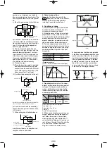
6. Self-diagnosis function

If a malfunction occurs, one of the following displays will appear.

Note 1: When the counter value goes below the minimum value during any of the subtraction, directive, independent, or phase input modes.
Note 2: Includes the possibility that the EEPROM’s life has expired.

or

02/2003

Summary of Contents for LC4H-PS-R4-AC240V

Page 1: ...tems 6 digit display Pin type Screw terminal type PRODUCT TYPES LC4H SV A rubber gasket ATC18002 and a mounting frame AT8 DA4 are included mm inch Digit Count speed Output Operation voltage Power down Additional function Terminal P N insurane Scale Factor 11 Pin LC4H PS R4 AC240V 100 240 V AC Scale Factor Screw LC4H PS R4 AC240VS with 12V DC power supply Scale Factor Voltage Signal Input 11 Pin LC...

Page 2: ...en collector 1 0 107 ope At rated control voltage 12 to 24 V DC 24 V AC Max 3 W 100 mA 30 V DC Transistor output type DC AC type Rating Contact Life Electrical Mechanical Operating conditions Rated operating voltage Rated frequency Rated power consumption Rated control capacity Input mode Max counting speed Counting input input 1 input 2 Reset input Lock input Input signal Output mode One shot out...

Page 3: ...ts are attached in a continuous series the dimension of A is Device installation rail ATA48011 sold separately Min 80 3 150 Min 80 3 150 95 5 112 9 3 760 4 445 45 0 6 0 1 772 024 0 45 0 6 0 1 772 024 0 45 0 6 0 1 772 024 0 A 48 n 2 5 0 6 0 With power supply for sensor NO NC 3 5 4 2 1 11 10 9 8 7 6 3 5 4 2 1 11 10 9 8 7 6 NO NC 3 5 4 2 1 11 10 9 8 7 6 0 V DC 12V 100mA Max 3 5 4 2 1 11 10 9 8 7 6 0 ...

Page 4: ...tor T Lock indicator Y UP keys Changes the corresponding digit of the set value in the addition direction upwards U DOWN keys Changes the corresponding digit of the set value in the subtraction direction down wards I RESET switch Resets the counting value and the output O SET LOCK switch This is used to handle pre scaling values one shot times decimal point position set tings and key lock operatio...

Page 5: ...dent and phase inputs The counting value is counted up or down to any number other than 0 once When it comes to 0 zero again the counter starts counting up E The decimal point is set using the UP and DOWN keys to specify the 2nd 3rd and 4th digits this applies only to 4 digit models The 1st digit is set using the UP key or DOWN key in settings where there is no decimal point this applies only to 4...

Page 6: ... IN2 are completely independent so there is no restriction on signal timing IN1 is the counting input and IN2 is the addition or subtraction directive input IN2 adds at L level and subtracts at H level IN1 is addition input and IN2 is subtrac tion input Addition when the IN1 phase advances beyond IN2 and subtraction when the IN2 phase advances beyond IN1 0 1 2 3 n 3 n 2 n 1 n n n 1 n 2 n 3 3 2 1 0...

Page 7: ...ultaneous with completion of count up While output is being main tained restarting of the count is not possible n Set value One shot Recount II SHOT C Output control is maintained after count up completion for one shot output time Counting is possible despite com pletion of count up However reset occurs simultaneous with output OFF n Set value One shot Hold count SHOT D Output control is maintaine...

Page 8: ... Residual voltage during short circuit 2 V max Impedance when released 100 kΩ min Max applied voltage 40 VDC max Lock input specifications Impedance during short circuit 1 kΩ max At 0 Ω the outflow current is approximately 1 5 mA Residual voltage during short circuit 2 V max Impedance when released 100 kΩ min Max applied voltage 40 DVC max The contact relay should be one which can open close 5 V 1...

Page 9: ...the count value use contacts with as short a bounce time as possible In general select Input 1 and Input 2 to have a maximum counting speed of 30 Hz and to be reset with a minimum input signal width of 20 ms 2 Non contact point input Connect with an open collector Use transistors whose characteristics satisfy the criteria given below VCEO 20 V min IC 20 mA min ICBO 6µA max Also use transistors wit...

Page 10: ... polar full wave voltage Operating voltage Surge voltage peak value AC type 6 000V DC type 24V AC type Power supply terminals Input terminals AC type DC type 24V AC type Noise voltage 1 500V 1 000V 600V 1 000V Peak value 0 0 1 2 50 30 50 90 100 Time µs Surge voltage C C C R Fig A Fig B Operation power supply Leakage current R C Operation power supply R R C C R R Relay Counter Receive output from c...

Page 11: ...ing use dou ble insulated relays etc 2 Always connect loads insulated with basic insulation specifications to the out put contact points The counter unit is also insulated with basic insulation speci fications The combination of the two sat isfies VDE which calls for double insula tion 3 For the applied power supply use one protected by an over current protec tion device that conforms with EN IEC ...

Reviews: