70
KX-TG6700BXB/KX-TGA670BXB
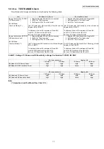
10.1.9.3. Check Table for RF part
Note:
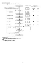
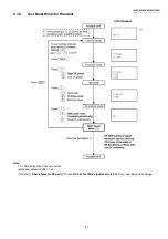
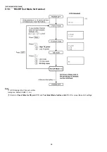
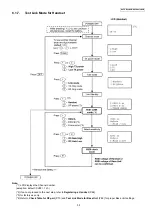
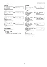
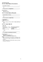
Adjustment and Test Mode Flow Chart
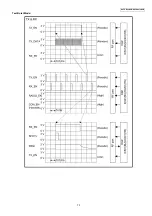
RF-DSP Interface Signal Wave Form
X501 (Base Unit), X201 (Handset) Check
No.
Item
BU (Base Unit) Check
HS (HandSet) Check
1
Link Confirmation Normal
HS, BU Mode [Normal Mode]
1. Register Regular HS to BU (to be
checked).
2. Press [Talk] key of the Regular HS to
establish link.
1. Register HS (to be checked) to Regular
BU.
2. Press [Talk] key of the HS to establish link.
2
Control signal confirmation
HS, BU Mode: [Test Burst Mode] (*1)
Check DSP interface. (*2)
Check DSP interface. (*2)
3
X’tal Frequency confirmation (*7)
HS, BU Mode: [Adjustment] (*3)
Check X’tal Frequency.
(13.824000 MHz ±270 Hz)
Check X’tal Frequency.
(13.824000 MHz ±100 Hz)
4
TX Power confirmation
Regular HS, BU Mode:
[RX-CW Mode.] (*4)
HS, BU (to be checked) Mode:
[Test Burst Mode.] (*1)
1. Place the Regular HS about 15 cm away
from the BU.
2. Confirm that RSSI of the Regular HS is
approximately 2 V by Oscilloscope. (*5)
1. Place the HS about 15 cm away from the
Regular BU.
2. Confirm that RSSI of the Regular BU is
approximately 2 V by Oscilloscope. (*6)
5
RX Sensitivity confirmation
Regular HS, BU Mode:
[Test Burst Mode.] (*1)
HS, BU (to be checked) Mode:
[RX-CW Mode.] (*4)
1. Place the Regular HS about 15cm away
from the BU.
2. Confirm that RSSI of the BU is
approximately 2 V by Oscilloscope. (*5)
1. Place the HS about 15 cm away from the
Regular BU.
2. Confirm that RSSI of the HS is
approximately 2 V by Oscilloscope. (*6)
6
Range Confirmation Normal
HS, BU Mode: [Normal Mode]
1. Register Regular HS to BU (to be
checked).
2. Press [Talk] key of the Regular HS to
establish link.
3. Compare the range of the BU (being
checked) with that of the Regular BU.
1. Register HS (to be checked) to Regular
BU.
2. Press [Talk] key of the HS to establish link.
3. Compare the range of the HS (being
checked) with that of the Regular HS.
Summary of Contents for KX-TG6700BXB
Page 2: ...2 KX TG6700BXB KX TGA670BXB ...
Page 6: ...6 KX TG6700BXB KX TGA670BXB 3 Specifications ...
Page 35: ...35 KX TG6700BXB KX TGA670BXB 4 11 Signal Route Each signal route is as follows ...
Page 36: ...36 KX TG6700BXB KX TGA670BXB RF part signal route ...
Page 40: ...40 KX TG6700BXB KX TGA670BXB 6 1 2 Connecting the Telephone Line Cord ...
Page 41: ...41 KX TG6700BXB KX TGA670BXB 6 1 2 1 If you subscribe to a DSL service ...
Page 43: ...43 KX TG6700BXB KX TGA670BXB 6 4 1 Battery Level 6 4 2 Panasonic Battery Performance ...
Page 46: ...46 KX TG6700BXB KX TGA670BXB ...
Page 47: ...47 KX TG6700BXB KX TGA670BXB 7 2 2 Programming Using the Direct Commands ...
Page 48: ...48 KX TG6700BXB KX TGA670BXB ...
Page 49: ...49 KX TG6700BXB KX TGA670BXB 7 3 Error Messages ...
Page 50: ...50 KX TG6700BXB KX TGA670BXB 7 4 Troubleshooting ...
Page 51: ...51 KX TG6700BXB KX TGA670BXB ...
Page 52: ...52 KX TG6700BXB KX TGA670BXB ...
Page 72: ...72 KX TG6700BXB KX TGA670BXB 10 1 9 5 RF DSP Interface Signal Wave Form Test Burst Mode ...
Page 73: ...73 KX TG6700BXB KX TGA670BXB Test Burst Mode ...
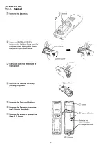
Page 80: ...80 KX TG6700BXB KX TGA670BXB 11 1 2 Handset ...
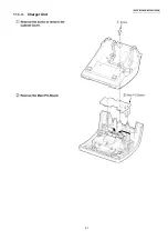
Page 81: ...81 KX TG6700BXB KX TGA670BXB 11 1 3 Charger Unit ...
Page 93: ...93 KX TG6700BXB KX TGA670BXB Memo ...
Page 97: ...97 KX TG6700BXB KX TGA670BXB Memo ...
Page 106: ...106 KX TG6700BXB KX TGA670BXB Memo ...
Page 116: ...116 KX TG6700BXB KX TGA670BXB 15 3 Explanation of IC Terminals RF Part 15 3 1 IC701 ...
Page 117: ...117 KX TG6700BXB KX TGA670BXB 15 3 2 IC801 Backside Terminal GND ...
Page 118: ...118 KX TG6700BXB KX TGA670BXB 15 3 3 IC851 Backside Terminal GND ...
Page 122: ...122 KX TG6700BXB KX TGA670BXB 16 3 Cabinet and Electrical Parts Charger Unit ...
Page 123: ...123 KX TG6700BXB KX TGA670BXB 16 4 Accessories and Packing Materials 16 4 1 KX TG6700BXB ...
Page 124: ...124 KX TG6700BXB KX TGA670BXB 16 4 2 KX TGA670BXB ...

