17
KX-TG6700BXB/KX-TGA670BXB
4.5.5.
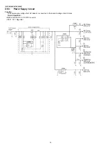
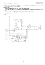
Telephone Line Interface
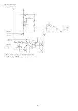
Telephone Line Interface Circuit:
Function
• Bell signal detection
• ON/OFF hook and pulse dial circuit
• Side tone circuit
4.5.5.1.
Line 1
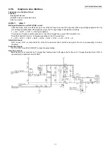
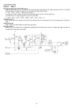
Bell signal detection and OFF HOOK circuit:
In the idle mode, Q141 and Q142 are open to cut the DC loop current and the ring load. When ring voltage appears at the Tip
(T) and Ring (R) leads (When the telephone rings), the AC ring voltage is transferred as follows:
T
→
L101
→
R111
→
PC111
→
DSP pin 72 [BELL]
To provide an off-hook condition (active DC current flow through the circuit), CPU turns Q145 on.
Thus Q141 and Q142 turn on. Following signal flow is the DC current flow.
T
→
L101
→
D101
→
Q141
→
Q161
→
R163
→
Q142
→
D101
→
L102
→
P101
→
R
ON HOOK Circuit:
Q141 is open, Q141 is connected as to cut the DC loop current and to cut the voice signal. The unit is consequently in on-hook
condition.
Pulse Dial Circuit:
Pin 73 of DSP turns Q145 ON/OFF to make the pulse dialing.
Side Tone Circuit:
Basically this circuit prevents the TX signal from feeding back to RX signal. As for this unit, TX signal feed back from Q161 is
canceled by the canceller circuit of DSP.
Summary of Contents for KX-TG6700BXB
Page 2: ...2 KX TG6700BXB KX TGA670BXB ...
Page 6: ...6 KX TG6700BXB KX TGA670BXB 3 Specifications ...
Page 35: ...35 KX TG6700BXB KX TGA670BXB 4 11 Signal Route Each signal route is as follows ...
Page 36: ...36 KX TG6700BXB KX TGA670BXB RF part signal route ...
Page 40: ...40 KX TG6700BXB KX TGA670BXB 6 1 2 Connecting the Telephone Line Cord ...
Page 41: ...41 KX TG6700BXB KX TGA670BXB 6 1 2 1 If you subscribe to a DSL service ...
Page 43: ...43 KX TG6700BXB KX TGA670BXB 6 4 1 Battery Level 6 4 2 Panasonic Battery Performance ...
Page 46: ...46 KX TG6700BXB KX TGA670BXB ...
Page 47: ...47 KX TG6700BXB KX TGA670BXB 7 2 2 Programming Using the Direct Commands ...
Page 48: ...48 KX TG6700BXB KX TGA670BXB ...
Page 49: ...49 KX TG6700BXB KX TGA670BXB 7 3 Error Messages ...
Page 50: ...50 KX TG6700BXB KX TGA670BXB 7 4 Troubleshooting ...
Page 51: ...51 KX TG6700BXB KX TGA670BXB ...
Page 52: ...52 KX TG6700BXB KX TGA670BXB ...
Page 72: ...72 KX TG6700BXB KX TGA670BXB 10 1 9 5 RF DSP Interface Signal Wave Form Test Burst Mode ...
Page 73: ...73 KX TG6700BXB KX TGA670BXB Test Burst Mode ...
Page 80: ...80 KX TG6700BXB KX TGA670BXB 11 1 2 Handset ...
Page 81: ...81 KX TG6700BXB KX TGA670BXB 11 1 3 Charger Unit ...
Page 93: ...93 KX TG6700BXB KX TGA670BXB Memo ...
Page 97: ...97 KX TG6700BXB KX TGA670BXB Memo ...
Page 106: ...106 KX TG6700BXB KX TGA670BXB Memo ...
Page 116: ...116 KX TG6700BXB KX TGA670BXB 15 3 Explanation of IC Terminals RF Part 15 3 1 IC701 ...
Page 117: ...117 KX TG6700BXB KX TGA670BXB 15 3 2 IC801 Backside Terminal GND ...
Page 118: ...118 KX TG6700BXB KX TGA670BXB 15 3 3 IC851 Backside Terminal GND ...
Page 122: ...122 KX TG6700BXB KX TGA670BXB 16 3 Cabinet and Electrical Parts Charger Unit ...
Page 123: ...123 KX TG6700BXB KX TGA670BXB 16 4 Accessories and Packing Materials 16 4 1 KX TG6700BXB ...
Page 124: ...124 KX TG6700BXB KX TGA670BXB 16 4 2 KX TGA670BXB ...

