background image

Installation

76

Installation Manual

14.

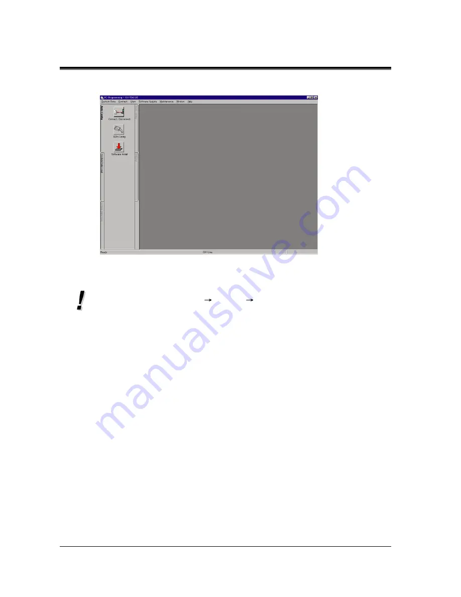
The initial screen is displayed.

If you want to remove the installed TD 612 PC programming software, start the procedure 
from clicking Uninstall (Start 

 Program 

 TD612PC) or double-click Setup.exe 

(which you started when installing) and follow the directions. Please do not attempt a 
different method of uninstalling the software.

For further information, refer to "Help" of PC programming software and "PC 
Programming (page 11-15)" in Getting Started manual.

Summary of Contents for KX-TD612E

Page 1: ...rid System Installation Manual Version 3 Thank you for purchasing a Panasonic Digital Super Hybrid System Model KX TD612 Please read this manual before connecting the Digital Super Hybrid System and s...

Page 2: ...ments and other relevant provisions of Directive 1999 5 EC If you want to get a copy of the original Declaration of Conformity of our products which relates to the R TTE please contact to our web addr...

Page 3: ...HONE 12 CO DPT with SP PHONE 24 CO DPT with SP PHONE 1 Line Display 12 CO DPT with SP PHONE 3 Line Display 24 CO DPT with SP PHONE 6 Line Display 24 CO Console KX T7240 KX T7440 KX T7441 Digital DSS C...

Page 4: ...cover is obtained A replacement fuse cover can be purchased from your local Panasonic Dealer IF THE FITTED MOULDED PLUG IS UNSUITABLE FOR THE SOCKET OUTLET IN YOUR HOME THEN THE FUSE SHOULD BE REMOVE...

Page 5: ...is prevented Failure to prevent such user access will invalidate any approval given to this apparatus CAUTION Do not push the PAUSE button more than twice following the initial access digit or digits...

Page 6: ...the European Telecommunication Standards ETS specifications below ETS 300 092 Calling Line Identification Presentation CLIP supplementary service ETS 300 093 Calling Line Identification Restriction CL...

Page 7: ...DISCONNECTING THE POWER CONNECTION PRIOR TO RELOCATING THE EQUIPMENT AND RECONNECT THE POWER FIRST THIS UNIT IS EQUIPPED WITH AN EARTHING CONTACT PLUG FOR SAFETY REASONS THIS PLUG MUST ONLY BE CONNECT...

Page 8: ...with the RS 232C port of the unit You should note the serial number of this unit in the space provided and retain this book as a permanent record of your purchase to aid in identification in the even...

Page 9: ...and connection diagram Section 2 Installation Contains the basic system installation and wiring instructions as well as how to install the optional cards Section 3 Troubleshooting Provides information...

Page 10: ...ension Connection 41 2 4 4 EXtra Device Port XDP Parallelled Telephone Connection 44 2 4 5 Doorphone and Door Opener Connection 48 2 4 6 External Relay and Second Ringer Relay Connection 51 2 4 7 Exte...

Page 11: ...0 System Restart 79 2 10 1 System Restart 79 2 11 System Data Default Set 80 2 11 1 System Data Default Set 80 3 Troubleshooting 3 1 Troubleshooting 82 3 1 1 Installation 82 3 1 2 Connection 83 3 1 3...

Page 12: ...Table of Contents 12 Installation Manual...

Page 13: ...System Outline Installation Manual 13 Section 1 System Outline This section provides general information on the system including system capacity and connection diagram...

Page 14: ...twork ISDN or the caller s identification number CLIP Built in Voice Message Enables you to store a voice message transferred from internal external calls if an optional card KX TD61291 is installed i...

Page 15: ...sion jacks 1 to 4 in the system also supports a parallel connection of a digital proprietary telephone and a single line device They share the same extension number and are considered by the system to...

Page 16: ...System Outline 16 Installation Manual Uniform Call Distribution UCD Allows incoming calls to be distributed uniformly to a specific group of extensions...

Page 17: ...with optional components or customer supplied peripherals such as external speakers external music sources e g radios and door openers To ISDN BRI port 1 and 2 initial To ISDN BRI port 3 additional Li...

Page 18: ...splay proprietary telephone Parallel connection of telephone is possible Refer to section 2 4 4 EXtra Device Port XDP Parallelled Telephone Connection Extension jacks 1 to 4 are available for eXtra De...

Page 19: ...Control Method Stored Programme Control ROM Control RAM MC68302 CPU 16 bit 14 7 MHz 40 Mbit Flash memory 8 Mbit SRAM Switching Non Blocking PCM Time Sharing Switch Power Supplies Primary Secondary 11...

Page 20: ...W Backup Batteries Total voltage 24 V DC Maximum Current 2 3 A CentralOfficeLoop Limit 1 600 max Environmental Requirements 0 C 40 C 10 90 relative humidity no condensation Door Opener 60 V DC 1 A ma...

Page 21: ...System Outline Installation Manual 21 Extension Groups 8 Class of Service 8 Hunting Group 32 Item Maximum Quantity...

Page 22: ...System Outline 22 Installation Manual...

Page 23: ...Installation Installation Manual 23 Section 2 Installation This section contains the basic system installation and wiring instructions as well as how to install the optional cards...

Page 24: ...d hot cold or humid places Temperature range 0 C 40 C 2 Sulfuric gases produced in areas where there are thermal springs etc may damage the equipment or contacts 3 Places in which shocks or vibrations...

Page 25: ...ucture 7 Mis wiring may cause the system to operate improperly Refer to section 3 1 1 Installation and section 3 1 2 Connection 8 If an extension does not operate properly disconnect the telephone fro...

Page 26: ...n of the Main Unit 2 2 1 Unpacking Unpack the box and confirm the items below Main Unit 1 AC Cord 1 Screws for wall mounting 3 Washers for wall mounting 3 Pin Plug 2 8 pin Terminal Block for extension...

Page 27: ...s AC Inlet Power Switch Power Indicator Extension Connectors External Music Jack ISDN BRI Line Modular Jacks Serial Interface RS 232C Paging Jack Battery Interface Ground Terminal External Equipment C...

Page 28: ...f the main unit If screws other than the ones supplied are used use the same sized diameter screws as the enclosed ones Two ways of mounting are shown below Mounting on a Wooden Wall 1 Place the templ...

Page 29: ...a wall to mark the screw positions 2 Drill holes and drive the rawlplugs user supplied with a hammer flush to the wall 3 Install the screws included into the rawlplugs 4 Hook the main unit on the scr...

Page 30: ...roper grounding connection to the earth ground is very important to protect the system from the bad effect of external noise or to reduce the electric shock of a lightning strike The GND pin of the 3...

Page 31: ...0 included A When your contract is point to point B When your contract is point to multipoint B 1 Your system is at the end of the connection B 2 Your system is not at the end of the connection CAUTIO...

Page 32: ...acsimiles or personal computers connected to the ISDN BRI ports port 2 and port 3 on the main unit KX TD612 A maximum of 8 ISDN extensions can be connected to each ISDN BRI port Be sure to place termi...

Page 33: ...RS 232C port ISDN extension port 2 or 3 Notice While executing software installation or system data download by PC programming software do not use the telephone system since software system change or...

Page 34: ...Installation 34 Installation Manual From Your KX TD612 to Other KX TD612 From Other KX TD612 to Your KX TD612 Computer To Central Office...

Page 35: ...n the screw 2 Remove the top front cover Closing the top front cover 1 Replace the covers and tighten the screws 2 Tie together all of the connected cords and attach them to the wall so that the cords...

Page 36: ...d for CO lines or ISDN extension lines default Port 2 CO Port 3 Extension To use ISDN extension lines some System Programming and hardware changes are required beforehand A To make 4 CO lines 1 Insert...

Page 37: ...e an internal power supply set the power supply jumper cover to the ON position as below b To use ISDN BRI ports as CO line ports set the power supply jumper cover to the OFF position 2 Insert the mod...

Page 38: ...2 Permanent Port 3 Call 424 ISDN Configuration Default Port 1 2 Point Port 3 Multipoint 425 ISDN Data Link Mode Default Port 1 2 Permanent Port 3 Call 426 ISDN TEI Mode Default Port 1 2 Fix 0 Port 3 A...

Page 39: ...able which is 10 m above ground can be as high as 200 000 volts This system should be installed with lightning protectors In addition grounding connection to earth ground is very important for the pro...

Page 40: ...mple is only a recommendation The length of the earth rod and required depth depend on the composition of the soil 1 Installation location of the earth rod 2 Check obstructions 3 Composition of the ea...

Page 41: ...le that connects the system and the extension is as follows Wire Diameter of conductor Solid wire 0 4 mm 0 6 mm Telephone Wiring Single line telephones 1 pair wire A B Digital proprietary telephones 2...

Page 42: ...ephones 1 While pressing down on the hole at the top of the terminal block using a screwdriver insert the required telephone wire into the side hole as shown below 2 Attach the terminal blocks to the...

Page 43: ...o the PBX main unit extension lines should be checked carefully If the extension lines are connected to the main unit with those wires making a short circuit between the H L pins or A B pins it may ca...

Page 44: ...Any single line telephone can be connected in parallel with a digital proprietary telephone Three examples of the connections are shown below System programming is required to determine the type of co...

Page 45: ...ingle Line Telephone 4 conductor wiring cord Connect pins A B H and L Back of the KX T7200 Series DPTs To system To single line telephone Note Ensure the cords are inserted in the grooves to prevent d...

Page 46: ...2 Connection through the Modular Socket Modular Socket 2 conductor wiring cord Connect pins A and B Digital Proprietary Telephone Single Line Telephone 4 conductor wiring cord Connect pins H and L on...

Page 47: ...T Adaptor Double Modular Socket 2 conductor wiring cord Connect pins A and B Digital Proprietary Telephone Single Line Telephone 4 conductor wiring cord For a digital proprietary telephone Connect pi...

Page 48: ...s as follows Installing the Doorphone 1 Loosen the screw to separate the doorphone into two halves 2 Attach the base cover to a wall using two screws Note Two kinds of screws are packed with KX T30865...

Page 49: ...the top of the terminal block using a screwdriver insert the telephone wire into the side hole as shown below 2 Attach the terminal block to the external equipment connector on the system 3 Connect t...

Page 50: ...Specifications for the current rating of the door opener contacts Programming Reference 122 Automatic Door Open Assignment 607 608 Doorphone Ringing Assignment Day Night Feature Reference Door Opener...

Page 51: ...2 documentation this second ringer is called Second Ringer Relay Never exceed the current ratings of the relay contacts Please see the current ratings in 1 3 1 Specifications Connection Use a 10 pin t...

Page 52: ...y is activated Pin 5 Pin 3 becomes open and Pin 5 Pin 4 becomes closed Pin 6 Pin 7 is normally open It becomes closed when the ringer relay rings 3 Connect the equipment cables to the external relay a...

Page 53: ...nce 600 Length of cable 18 22 AWG Under 10 m Shielded cable is recommended To adjust the sound level of the pager use the volume control on the amplifier Programming Reference 804 External Pager BGM 8...

Page 54: ...ance 600 Length of cable 18 22 AWG Under 10 m Shielded cable is recommended System programming for music sources used for Music on Hold and Background Music BGM is required To adjust the sound level o...

Page 55: ...nected to the system as shown in the chart on the following page The pin configuration of the Serial Interface RS 232C Connector is as follows It is possible to perform System Programming using a PC c...

Page 56: ...nly when all attempts at Internet access have failed with your PC What to change Use a cable that has pin 1 electrically connected to pin 6 at both ends Try again Internet Access Serial Interface RS 2...

Page 57: ...t An ON condition of circuit DR DSR indicates the printer or the PC is ready Circuit DR DSR ON does not indicate that communication has been established with the printer or the PC Signal Ground SG Con...

Page 58: ...n the main unit and on the optional cards If accessing the parts is required wear a grounding strap CAUTION Power off the system and unplug the AC cord before installing an optional card 1 BRI Expansi...

Page 59: ...nt cover 3 Attach the optional Analogue CO Expansion Card KX TD61281 or Caller ID Sending Card with 1 CO I F KX TD61283 to the system and connect the cord to the connector then secure the screw as sho...

Page 60: ...Connection 1 While pressing down on the hole at the top of the terminal block included using a screw driver insert the required wire into the side hole as shown below 2 Attach the terminal blocks to...

Page 61: ...nsion Card KX TD61280 and Voice Message Card KX TD61291 can be installed in the system 4 When an BRI expansion card is installed set the jumper cover on the card to the appropriate position as shown b...

Page 62: ...ly set the power supply jumper cover to the ON position as below b To use the ISDN port as the CO line port set the power supply jumper cover to the OFF position For CO line use Jumper Cover EXT S0 1...

Page 63: ...amming Reference 820 OGM Recording Feature Reference Built in Voice Message CO Line Connection Assignment CO Line Connection Assignment Outgoing Direct Inward System Access DISA Intelligent Call Handl...

Page 64: ...ine 422 ISDN Port Type Default Port 1 2 CO Port 3 Extension 423 ISDN Layer 1 Active Mode Default Port 1 2 Permanent Port 3 Call 424 ISDN Configuration Default Port 1 2 Point Port 3 Multipoint 425 ISDN...

Page 65: ...then secure the screw as shown below Note Be sure to connect the cord in such a way that the ferrite core is closer to the optional doorphone door opener card than to the main board The cord can be i...

Page 66: ...rew driver insert the required wire into the side hole as shown below 2 Attach the terminal blocks to each doorphone door opener connector a KX TD61260 Two 5 pin Connectors KX TD61260 Two 5 pin termin...

Page 67: ...Microphone Shield German type Doorphone Doorphone 3 Adaptor 220V BL L O U B OV L O U B 12V 8V Door Opener 3 To RT TS2 TS1 b a TO1 TO2 German type Doorphone Doorphone 2 Adaptor 220V BL L O U B OV L O...

Page 68: ...in the event of a power failure 1 Attach the cables KX A227 and 2 user supplied car batteries 12 V DC each as shown below Then insert the connector into the battery interface on the system Check the...

Page 69: ...in the system The system will continue to be powered even if the power switch is turned OFF The power supply cord is used as the main disconnect device Make sure that the outlet is located installed n...

Page 70: ...th the default values If the system does not work properly see section 2 11 1 System Data Default Set After pressing the reset button return the system clear switch to the NORMAL position in step 4 wh...

Page 71: ...MHz RAM 48 MB HDD 20 MB Recommendation of the ISDN cards for the remote maintenance FRITZ Card PCMCIA AVM FRITZ Card PCI AVM FRITZ Card classic AVM ELSA MicroLinkTM ISDN USB ELSA Xircom CreditCardTM...

Page 72: ...tion Procedure 1 Start Windows 2 After exiting all Windows programmes on your computer insert the CD ROM included into CD ROM drive 3 Click PC Programming Software Installer on the initial screen 4 Cl...

Page 73: ...al 73 7 Click Yes after reading and accepting the license agreement If you choose No you cannot install the TD612 PC programming software 8 Select a folder to save the installed files Normally you do...

Page 74: ...Installation Manual 9 Choose the model the country and the language and then click Next 10 Select a programme folder where the software will be held Normally you do not need to change Click Next to s...

Page 75: ...ete the installation 12 Start PC programming software which is in a pre assigned programme folder 13 Enter the password for the standard version which is TD612 and click OK When you start up the featu...

Page 76: ...art the procedure from clicking Uninstall Start Program TD612PC or double click Setup exe which you started when installing and follow the directions Please do not attempt a different method of uninst...

Page 77: ...ble to assign ISDN data automatically on PC programming software 1 Start PC programming software installed in your computer 2 Enter the password which is TD612 and then click OK 3 Click ISDN Config in...

Page 78: ...yed Port Type 422 ISDN Port Type Layer 1 Active Mode 423 ISDN Layer 1 Active Mode Access Mode 424 ISDN Configuration Data Link Mode L2 425 ISDN Data Link Mode TEI Assign 426 ISDN TEI Mode If you enter...

Page 79: ...re again to confirm whether there definitely is a problem or not System Restart causes the following Camp on is cleared Calls on Hold are cancelled Calls on Exclusive Hold are cancelled Calls in progr...

Page 80: ...onds return the system clear switch to the NORMAL position If successfully executed the DPTs should show the time as 0 00 CAUTION Before touching the system clear switch and reset button put on a grou...

Page 81: ...Troubleshooting Installation Manual 81 Section 3 Troubleshooting This section provides information for system and telephone troubleshooting...

Page 82: ...ion Press the reset button Noise in external paging Noise on the wire between the system and the amplifier Use a shielded cable as the connection wire between the system and amplifier A short shielded...

Page 83: ...for A B and outer 2 wires are for H L Connection between the system and a single line telephone Use the correct cord The inner 2 wires are for A B Connection between the system and a single line tele...

Page 84: ...versed Adjust the extension CO line socket as follows Jack 5 through 8 For DPT only If you cannot dial an extension Connection between the system and a digital proprietary telephone Use the correct co...

Page 85: ...Troubleshooting Installation Manual 85 Connection between the system and a single line telephone Connect a digital proprietary telephone...

Page 86: ...Programming Handset Headset Selection When the headset is not being used select the HANDSET mode by Station Programming The unit does not ring The Ringer Volume Selector is set to OFF Set to HIGH or...

Page 87: ...cleared by the following operation pressing the reset button and then setting the system clear switch to the NORMAL position while the power indicator is flashing within approximately 10 seconds Opera...

Page 88: ...Troubleshooting 88 Installation Manual e Set the system clear switch to the NORMAL position while the power indicator is flashing within approximately 10 seconds...

Page 89: ...Troubleshooting Installation Manual 89...

Page 90: ...o and telecommunications terminal equipment directive Copyright This manual is copyrighted by Kyushu Matsushita Electric Co Ltd KME You may print out this manual solely for internal use with this mode...

Reviews: