178
KX-FP701ME
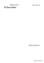
17.5. Interface Board (PCB5)
CN401
1
+6V
2
+6V
3
GND
4
GND
5
GND
6
+24V
7
+24V
8
+24V
IC403
1
S1
2
S2
3
S3
4
G
5
D1
6
D2
7
D3
8
D4
5.6k
R403
+24V
+3.3V
50
100n
C404
GND
+6V
CN402
1
2
3
4
5
IC401
1
I1
2
I2
3
I3
4
I4
5
I5
6
I6
7
I7
8
GND
9
COMMON
10
O7
11
O6
12
O5
13
O4
14
O3
15
O2
16
O1
Q401
B
C
E
+6V
F401
12
+24V
820
R405
1.5k
R407
D405
A
K
D403
A
K
GND
IC402
1
I1
2
I2
3
I3
4
I4
5
I5
6
I6
7
I7
8
GND
9
COMMON
10
O7
11
O6
12
O5
13
O4
14
O3
15
O2
16
O1
1.5k
R406
D404
A
K
GND
220
R402
+6V
D406
A
K
F402
12
Q402
B
C
E
+24V
820
R404
+24V
100
R409
35 33u
C405
GND
+3.3V
16
220u
C406
CN407
1
2
3
4
5
6
7
8
9
10
11
12
13
14
15
16
17
18
CN408
1
2
3
4
5
6
7
8
9
10
11
12
13
14
15
16
17
18
BA
T401
1
2
GND
2.2k
R408
D407
A
K
GND
CN405
1
2
3
GND
PS401
2
1
4
3
GND
CN406
1
COM
2
DATA
3
/STB2
4
GND
5
CLOCK
6
TM
7
+3.3V
8
GND
9
/STB1
10
LATCH
11
COM
GND
GND
50
100p
C402
50
100p
C403
GND
GND
+6V
+5V
+5V
+5V
CN404
1
2
3
4
5
6
7
8
50
100n
C401
180
R410
100
R401
CN403
1
2
3
4
5
D401
A
K
D402
A
K
HEADON
TM[0]
TM[1]
TM[2]
TM[3]
RM[0]
RM[1]
RM[2]
RM[3]
RXE
TM[3]
TM[1]
RM[1]
RM[0]
THLA
T
THD
A
T
THCLK
TM
STB2
STB1
TM[2]
TM[0]
TXE
RM[3]
RM[2]
STB1
TM
THCLK
STB2
THDAT
KSTART
KLATCH
KRXD
KTXD
KSCLK
OPRESET
OPRESET
KSCLK
KTXD
KRXD
KLATCH
KSTART
THLAT
HEADON
TXE
RXE
TO DIGITAL
TO DIGITAL
TO SENSOR
TO OPE
TO TX MOTOR
TO RX MOTOR
TO POWER
TO THERMAL HEAD
KX-FP70
1
ME
: INTERFACE BOARD
Summary of Contents for KX-FP701ME
Page 9: ...9 KX FP701ME 4 General Introduction 4 1 Error Message 4 1 1 Display 4 1 2 Report ...
Page 11: ...11 KX FP701ME 6 Technical Descriptions 6 1 Connection Diagram ...
Page 13: ...13 KX FP701ME 6 2 1 General Block Diagram ...
Page 15: ...15 KX FP701ME 6 3 2 Memory Map ...
Page 24: ...24 KX FP701ME 6 4 2 Block Diagram ...
Page 26: ...26 KX FP701ME ...
Page 68: ...68 KX FP701ME 11 2 2 Service Mode Settings Note The above values are the default values ...
Page 75: ...75 KX FP701ME Countermeasure ...
Page 76: ...76 KX FP701ME REFERENCE Test Mode P 60 ...
Page 77: ...77 KX FP701ME REFERENCE Test Mode P 60 ...
Page 78: ...78 KX FP701ME REFERENCE Test Mode P 60 ...
Page 79: ...79 KX FP701ME REFERENCE Test Mode P 60 ...
Page 80: ...80 KX FP701ME ...
Page 81: ...81 KX FP701ME ...
Page 82: ...82 KX FP701ME REFERENCE Test Mode P 60 ...
Page 86: ...86 KX FP701ME ...
Page 111: ...111 KX FP701ME ...
Page 118: ...118 KX FP701ME I O and Pin No Diagram ...
Page 120: ...120 KX FP701ME Other NG example while the power is ON and the LCD displays the following ...
Page 121: ...121 KX FP701ME 12 5 5 2 NG Example ...
Page 125: ...125 KX FP701ME 12 5 7 2 Troubleshooting Flow Chart ...
Page 129: ...129 KX FP701ME 12 5 9 5 Check the HOOK Switch SW101 ...
Page 131: ...131 KX FP701ME 12 5 11 Thermal Head Section Note Refer to Thermal Head P 25 ...
Page 132: ...132 KX FP701ME 13 Service Fixture Tools ...
Page 136: ...136 KX FP701ME 14 2 2 HOW TO REMOVE THE OPERATION PANEL BLOCK ...
Page 137: ...137 KX FP701ME 14 2 3 HOW TO REMOVE THE OPERATION BOARD AND LCD ...
Page 138: ...138 KX FP701ME 14 2 4 HOW TO REMOVE THE SEPARATION HOLDER AND EXIT ROLLER ...
Page 139: ...139 KX FP701ME 14 2 5 HOW TO REMOVE THE IMAGE SENSOR CIS ...
Page 140: ...140 KX FP701ME 14 2 6 HOW TO REMOVE THE THERMAL HEAD ...
Page 141: ...141 KX FP701ME 14 2 7 HOW TO REMOVE THE PLATEN ROLLER AND BACK COVER ...
Page 142: ...142 KX FP701ME 14 2 8 HOW TO REMOVE THE PICKUP ROLLER ...
Page 143: ...143 KX FP701ME 14 2 9 HOW TO REMOVE THE CASSETTE LEVER ...
Page 144: ...144 KX FP701ME 14 2 10 HOW TO REMOVE THE BOTTOM FRAME ...
Page 145: ...145 KX FP701ME 14 2 11 HOW TO REMOVE THE DIGITAL ANALOG SENSOR BOARDS ...
Page 146: ...146 KX FP701ME 14 2 12 HOW TO REMOVE THE POWER SUPPLY BOARD AND AC CORD ...
Page 147: ...147 KX FP701ME 14 2 13 HOW TO REMOVE THE MOTOR BLOCK AND SEPARATION ROLLER ...
Page 148: ...148 KX FP701ME 14 2 14 HOW TO REMOVE THE GEARS OF MOTOR BLOCK ...
Page 149: ...149 KX FP701ME 14 2 15 INSTALLATION POSITION OF THE LEAD WIRES ...
Page 163: ...163 KX FP701ME 16 1 4 Power Supply Board 16 1 5 Interface Board ...
Page 166: ...166 KX FP701ME 16 3 Test Chart 16 3 1 ITU T No 1 Test chart ...
Page 167: ...167 KX FP701ME 16 3 2 ITU T No 2 Test Chart ...
Page 168: ...168 KX FP701ME 16 3 3 Test Chart ...
Page 169: ...169 KX FP701ME MEMO ...
Page 180: ...180 KX FP701ME MEMO ...
Page 188: ...188 KX FP701ME MEMO ...
Page 194: ...194 KX FP701ME 20 1 2 Operation Panel Section ...
Page 195: ...195 KX FP701ME 20 1 3 Back Cover Section ...
Page 196: ...196 KX FP701ME ...
Page 197: ...197 KX FP701ME 20 1 4 Upper Cabinet Section ...
Page 198: ...198 KX FP701ME 20 1 5 Lower Cabinet Section ...
Page 199: ...199 KX FP701ME 20 1 6 Gear Block Section ...
Page 200: ...200 KX FP701ME 20 1 7 Screws ...
Page 201: ...201 KX FP701ME 20 1 8 Accessories and Packing Materials ...