


92
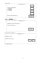
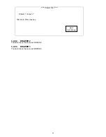
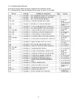
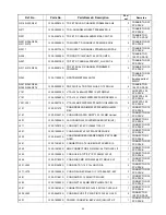
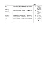
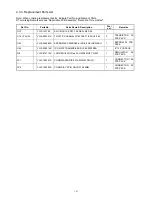
4.1.3. Replacement Parts List
Note: When ordering replacement parts, indicate Part No .and Name of Parts.
RTL marking Remarks means “Repairable PCB Assembly” “Retention Time Limited”.
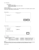
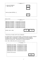
Ref. No.
Parts No.
Parts Name & Description
Pcs/
set
Remarks
U051
YJ30-123722
ASIC AU80586GE025D SLB73 C0 FC-BGA8 437P
1
U081
YJ30-123723
ASIC QG82945GSE SLB2R A3 FC-BGA3 998P
1
U141
YJ30-122709
ASIC ICH7-M 82801GBM PFBGA652
1
U152,U342
YJ32-110599S
IC SN74AHC1G08DBVR SOT-23 SMT5
2
IC 100 PCS
PACK
U162,U163
YJ30-526461S
EEPROM
2K 1.8V SO8 AT24C02BN-SH-T
2
IC 50 PCS PACK
Existing parts of
950WS
U191
YJ32-973876S
IC CLOCK ICS9LPRS501PGLFT TSSOP64 L/F
1 IC 10 PCS PACK
U202
YJ30-124167S
ASIC QFN64 88E8040A0-NNC1C000 MARVELL
1 IC 5 PCS PACK
U211,U365,U369
YJ32-110165S
IC
CMOS NC7S86P5X_NL SC70 FAIRCHILD LF
3
IC 100 PCS
PACK
U214,U302
YJ32-974592S
IC CONTROLLER TPS40211DGQR MSOP10
2 IC 5 PCS PACK
U221,U222
YJ32-191308S
IC CMOS SN74LVC1G125DBVR SOT23-5
2
IC 100 PCS
PACK
U225
YJ32-973604S
IC
VOLTAGE
TRANSLATOR PCA9306 VSSOP8
1 IC 20 PCS PACK
U241,U242,U243,
U244
YJ38-970001S
IC TVS D ARRAY NUP4201MR6T1G TSOP6 W/LF
4
IC 50 PCS
PACK
U251
YJ32-975388S
Regulator RT9166A-12PGL 1.2V SOT-223
1
REGULATOR 50
PCS PACK
U252
YJ30-124166S
ASIC IC 88SE6121B2-NAA2C000 QFN76
1 IC 5 PCS PACK
U261
YJ30-123324S
IC ASIC LPC I/O QFP128 W83627UHG REV:B
1 IC 5 PCS PACK
U271,U272,U281,
U291,U292
YJ32-970073S
IC MAX3243ECPWR TSSOP28
5 IC 10 PCS PACK
U293
YJ32-110015S
IC LMOS TC7S32FU(TE85L,F) SSOP5-P-A LF
1
IC 100 PCS
PACK
U301
YJ32-972165S
IC REGULATOR G905T24Uf 2.5V SOT-89 GMT
1
IC 100 PCS
PACK
U313
YJ32-975361S
IC CONTROLLER PM6686TR VFQFPN-32
1 IC 10 PCS PACK
U321
YJ32-974651S
IC CONTROLLER ISL8014IRZ-T QFN 16
1 IC 5 PCS PACK
U322
YJ32-974653S
IC REGULATOR TPS51200DRCR SON-10
1 IC 10 PCS PACK
U331,U332
YJ32-974282S
IC BUCK CONTROLLER NCP1589AMNTWG
DFN10
2 IC 20 PCS PACK
U341
YJ32-974996S
IC ADP3211AMNR2G QFN32
1 IC 10 PCS PACK
U361
YJ32-110185S
IC CMOS 74LVC08D SO14 PHILIPS
1
IC 50 PCS PACK
Existing parts of
950WS
U362
YJ32-974660S
IC ADM1815-R23ARTZ-RL SOT-23
1
U372,U373
YJ32-971543S
IC MIC841HYC5 SC70-5 (LF)
2 IC 10 PCS PACK
Q161
YJ35-950028S
TR DUAL FFB3904 SC70-6 FAIRCHILD
1
TRANSISTOR
100 PCS PACK
Summary of Contents for JS-925WS-010
Page 11: ...5 1 3 Outside drawing 12 Touch Screen 15 Touch Screen ...
Page 22: ...14 U214 U291 U292 U322 1 5V generation area 0 9V for Memory Terminator generation area ...
Page 25: ...17 U1 U2 U7 Audio AMP area ...
Page 27: ...19 U7 Q8 Y3 ...
Page 53: ...45 Please press 2 points ...
Page 66: ...58 3 5 13 BackLight Test Only OK NG ...
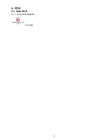
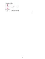
Page 67: ...59 4 PCB 4 1 Main PCB 4 1 1 Schematic Diagram p49_MAIN_schemati c pdf 40 pages ...
Page 69: ......
Page 74: ...96 4 2 Switch LED PCB 4 2 1 Schematic Diagram 93_SW LED_schematic pdf 3 pages ...
Page 75: ...97 4 2 2 Parts Location p95_SW LED_PCB pdf 1 page Total 4 pages ...
Page 77: ...99 4 3 Touch Panel PCB 4 3 1 Schematic Diagram p99_TOUCH PANEL_scematic pdf ...
Page 78: ...100 4 3 2 Parts Location p100_TOUCH PANEL PCB pdf ...
Page 80: ...102 4 4 JS 925CB 010 Optional I O PCB 4 4 1 Schematic Diagram p102_IO_schematic pdf 6 pages ...
Page 81: ...103 4 4 2 Parts Location p103_IO_PCB pdf 1page Total 7 pages ...
Page 82: ......
Page 84: ...110 4 5 JS 925HU 010 USB HUB PCB 4 5 1 Schematic Diagram p110_USB_schemati c pdf 4 pages ...
Page 85: ...111 4 5 2 Parts Location p111_USB_PCB pdf ...
Page 86: ......
Page 91: ...119 1 3 Disconnect Cables 1 4 Remove 4 screws 1 5 Lift up LCD Unit 1 6 Remove 2 screws ...
Page 92: ...120 1 7 Remove LCD unit Connect Earth Cable such as the following picture in case of assembly ...
Page 94: ...122 2 4 ...
Page 96: ...124 3 4 Disconnect the cable 3 5 Remove the 2 screws 3 6 Remove Front PCB ...
Page 97: ...125 3 7 Disconnect the cable 7 8 28 ...
Page 98: ...126 3 8 Remove the 2 screws 3 9 Remove Power Supply Shield 9 ...
Page 99: ...127 Check some points as shown in the following pictures in case of assembly ...
Page 100: ...128 ...
Page 101: ...129 3 10 Disconnect the cable 10 ...
Page 103: ...131 11 ...
Page 106: ...134 4 4 Remove the 2 screws 4 5 Remove PCB Shield such as shown in the following picture ...
Page 107: ...135 4 5 Disconnect the cable 4 6 Disconnect the cable 30 ...
Page 108: ...136 4 7 Remove the 4 screws 4 8 Remove HDD 13 14 15 ...
Page 109: ...137 4 9 Remove the 3 screws 4 10 Disconnect the cable 4 11 Remove Communication Board ...
Page 110: ...138 JS 925CB 010 4 12 Remove the 11 screws 4 13 Disconnect the cables ...
Page 111: ...139 4 14 Remove Main PCB 4 15 Remove DIMM 16 ...
Page 112: ...140 Side A Side B 17 ...
Page 114: ...142 5 Removal Base Frame 5 1 Remove the 2 screws ...
Page 115: ...143 5 2 Remove the 2 screws 5 3 Remove the base frame ...
Page 116: ...144 5 4 Remove the 2 screws 5 5 Remove I O Panel 29 ...
Page 117: ...145 5 6 Remove the 4 hex screws 5 7 Remove the 2 connector cables 18 19 ...
Page 118: ...146 20 ...
Page 119: ...147 5 8 Remove the 3 screws 5 9 Remove the 2 pillars 23 22 21 ...
Page 120: ...148 5 10 Remove 5 screws 24 25 26 27 ...
Page 124: ...152 3 Remove the 2 screws 4 Disconnect USB Hub Board JS 925HU 010 JS 925HU 010 ...
Page 125: ...153 5 Remove the 2 screws 6 Remove the 4 screws 7 Remove Hinge ...
Page 126: ...154 103 8 Loosen the 4 screws until sounds clicky 9 Remove the 4 screws 104 ...
Page 127: ...155 10 Open Display Front Cover 105 11 Remove the 4 screws ...
Page 128: ...156 12 Lift up TP LCD Then disconnect Backlight Cables 13 Disconnect LCD cable ...
Page 129: ...157 14 Disconnect Touch Panel Cable 15 Open TP LCD ...
Page 130: ...158 16 Remove the 4 screws 17 Remove the tape 116 117 ...
Page 131: ...159 18 Separate Touch Panel and LCD 106 107 ...
Page 132: ...160 19 Remove the 3 screws And remove Inverter Board 108 ...
Page 133: ...161 20 Remove the 2 screws And remove Touch Panel Control Board 109 21 Remove the Cables ...
Page 134: ...162 110 113 111 114 ...
Page 137: ...165 3 Remove the 2 screws 4 Disconnect USB Hub Board JS 925HU 010 JS 925HU 010 ...
Page 138: ...166 5 Remove the 2 screws 6 Remove the 4 screws 7 Remove Hinge ...
Page 139: ...167 203 ...
Page 142: ...170 14 Disconnect Touch Panel Cable 15 Open TP LCD ...
Page 143: ...171 16 Remove the 4 screws 17 Remove the tape ...
Page 144: ...172 18 Separate Touch Panel and LCD 206 207 ...
Page 145: ...173 19 Remove the 3 screws And remove Inverter Board 208 ...
Page 146: ...174 20 Remove the 2 screws And remove Touch Panel Control Board 209 21 Remove the Cables ...
Page 147: ...175 210 213 211 214 ...
Page 188: ...216 ...


