


193
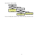
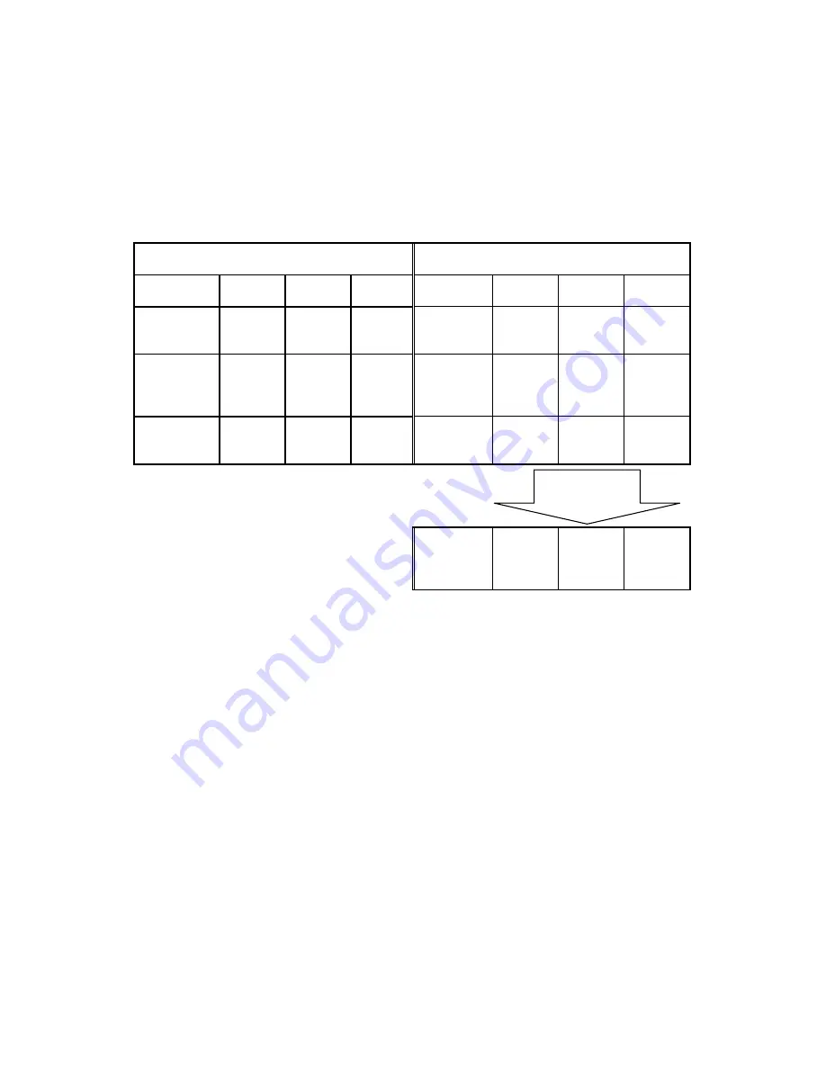
4.Detection of Drawer Status Switch
The state of Open/ Close of Drawer is shown in the table below by the type of the status switch of connected
Drawer. Under such a condition, the state of Open/ Close of Drawer of Normal close type reverses. Here, the
state of Open/ Close of Drawer can be matched by reversing the relation between the state of POS Hardware
Signal Level and the state of the Open/ Close with software.
It comes to be able to select the state of Open/ Close at No Drawer by combining and selecting the inverting
function of this Open/ Close and type of Status Switch of Drawer.
Drawer Status Switch:
Normal open type
ON: Open / OFF: Close
Drawer Status Switch:
Normal close type
ON: Close / OFF: Open
No
Drawer
Drawer
Close
Drawer
Open
No
Drawer
Drawer
Close
Drawer
Open
Drawer
Status
Switch
- OFF
ON
Drawer
Status
Switch
- ON
OFF
POS
Hardware
Signal
Level
Low High Low
POS
Hardware
Signal
Level
Low Low High
Software
Drawer
Status
Open Close Open
Software
Drawer
Status
Open Open Close
Software
Drawer
Status
(Reverse)
Close Close Open
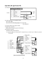
5.Connection of Normal close type RJ Drawer
(1)Single Drawer connection
Direct connect to RJ type connector of POS Terminal
(2)Dual Drawer connection
Use Branch cable of Normal close type
*
1
) Connect the Drawer with Drawer port #1 connector when you connect only one Drawer by using the
branch cable
Reversed
by Software
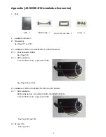
Summary of Contents for JS-925WS-010
Page 11: ...5 1 3 Outside drawing 12 Touch Screen 15 Touch Screen ...
Page 22: ...14 U214 U291 U292 U322 1 5V generation area 0 9V for Memory Terminator generation area ...
Page 25: ...17 U1 U2 U7 Audio AMP area ...
Page 27: ...19 U7 Q8 Y3 ...
Page 53: ...45 Please press 2 points ...
Page 66: ...58 3 5 13 BackLight Test Only OK NG ...
Page 67: ...59 4 PCB 4 1 Main PCB 4 1 1 Schematic Diagram p49_MAIN_schemati c pdf 40 pages ...
Page 69: ......
Page 74: ...96 4 2 Switch LED PCB 4 2 1 Schematic Diagram 93_SW LED_schematic pdf 3 pages ...
Page 75: ...97 4 2 2 Parts Location p95_SW LED_PCB pdf 1 page Total 4 pages ...
Page 77: ...99 4 3 Touch Panel PCB 4 3 1 Schematic Diagram p99_TOUCH PANEL_scematic pdf ...
Page 78: ...100 4 3 2 Parts Location p100_TOUCH PANEL PCB pdf ...
Page 80: ...102 4 4 JS 925CB 010 Optional I O PCB 4 4 1 Schematic Diagram p102_IO_schematic pdf 6 pages ...
Page 81: ...103 4 4 2 Parts Location p103_IO_PCB pdf 1page Total 7 pages ...
Page 82: ......
Page 84: ...110 4 5 JS 925HU 010 USB HUB PCB 4 5 1 Schematic Diagram p110_USB_schemati c pdf 4 pages ...
Page 85: ...111 4 5 2 Parts Location p111_USB_PCB pdf ...
Page 86: ......
Page 91: ...119 1 3 Disconnect Cables 1 4 Remove 4 screws 1 5 Lift up LCD Unit 1 6 Remove 2 screws ...
Page 92: ...120 1 7 Remove LCD unit Connect Earth Cable such as the following picture in case of assembly ...
Page 94: ...122 2 4 ...
Page 96: ...124 3 4 Disconnect the cable 3 5 Remove the 2 screws 3 6 Remove Front PCB ...
Page 97: ...125 3 7 Disconnect the cable 7 8 28 ...
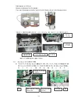
Page 98: ...126 3 8 Remove the 2 screws 3 9 Remove Power Supply Shield 9 ...
Page 99: ...127 Check some points as shown in the following pictures in case of assembly ...
Page 100: ...128 ...
Page 101: ...129 3 10 Disconnect the cable 10 ...
Page 103: ...131 11 ...
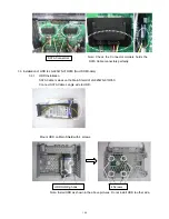
Page 106: ...134 4 4 Remove the 2 screws 4 5 Remove PCB Shield such as shown in the following picture ...
Page 107: ...135 4 5 Disconnect the cable 4 6 Disconnect the cable 30 ...
Page 108: ...136 4 7 Remove the 4 screws 4 8 Remove HDD 13 14 15 ...
Page 109: ...137 4 9 Remove the 3 screws 4 10 Disconnect the cable 4 11 Remove Communication Board ...
Page 110: ...138 JS 925CB 010 4 12 Remove the 11 screws 4 13 Disconnect the cables ...
Page 111: ...139 4 14 Remove Main PCB 4 15 Remove DIMM 16 ...
Page 112: ...140 Side A Side B 17 ...
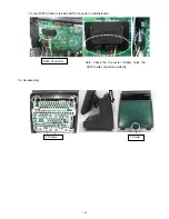
Page 114: ...142 5 Removal Base Frame 5 1 Remove the 2 screws ...
Page 115: ...143 5 2 Remove the 2 screws 5 3 Remove the base frame ...
Page 116: ...144 5 4 Remove the 2 screws 5 5 Remove I O Panel 29 ...
Page 117: ...145 5 6 Remove the 4 hex screws 5 7 Remove the 2 connector cables 18 19 ...
Page 118: ...146 20 ...
Page 119: ...147 5 8 Remove the 3 screws 5 9 Remove the 2 pillars 23 22 21 ...
Page 120: ...148 5 10 Remove 5 screws 24 25 26 27 ...
Page 124: ...152 3 Remove the 2 screws 4 Disconnect USB Hub Board JS 925HU 010 JS 925HU 010 ...
Page 125: ...153 5 Remove the 2 screws 6 Remove the 4 screws 7 Remove Hinge ...
Page 126: ...154 103 8 Loosen the 4 screws until sounds clicky 9 Remove the 4 screws 104 ...
Page 127: ...155 10 Open Display Front Cover 105 11 Remove the 4 screws ...
Page 128: ...156 12 Lift up TP LCD Then disconnect Backlight Cables 13 Disconnect LCD cable ...
Page 129: ...157 14 Disconnect Touch Panel Cable 15 Open TP LCD ...
Page 130: ...158 16 Remove the 4 screws 17 Remove the tape 116 117 ...
Page 131: ...159 18 Separate Touch Panel and LCD 106 107 ...
Page 132: ...160 19 Remove the 3 screws And remove Inverter Board 108 ...
Page 133: ...161 20 Remove the 2 screws And remove Touch Panel Control Board 109 21 Remove the Cables ...
Page 134: ...162 110 113 111 114 ...
Page 137: ...165 3 Remove the 2 screws 4 Disconnect USB Hub Board JS 925HU 010 JS 925HU 010 ...
Page 138: ...166 5 Remove the 2 screws 6 Remove the 4 screws 7 Remove Hinge ...
Page 139: ...167 203 ...
Page 142: ...170 14 Disconnect Touch Panel Cable 15 Open TP LCD ...
Page 143: ...171 16 Remove the 4 screws 17 Remove the tape ...
Page 144: ...172 18 Separate Touch Panel and LCD 206 207 ...
Page 145: ...173 19 Remove the 3 screws And remove Inverter Board 208 ...
Page 146: ...174 20 Remove the 2 screws And remove Touch Panel Control Board 209 21 Remove the Cables ...
Page 147: ...175 210 213 211 214 ...
Page 188: ...216 ...


